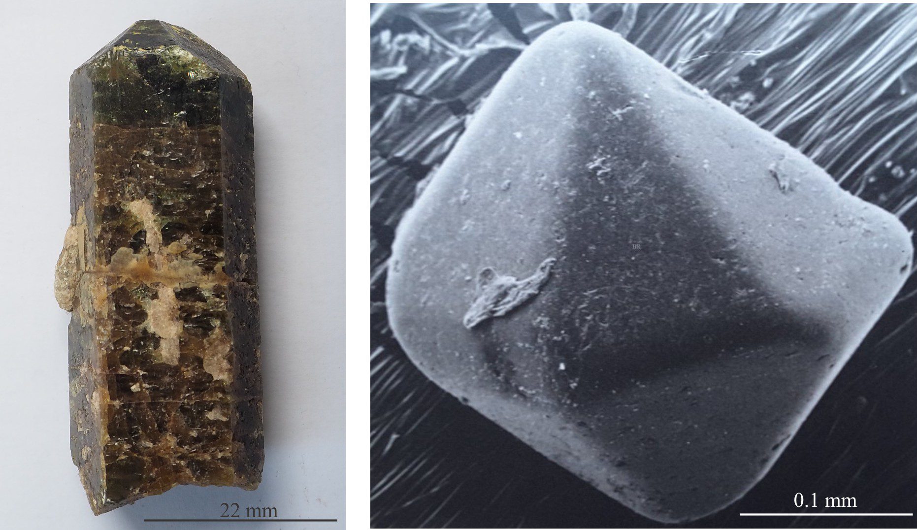
Minerals are defined by their chemical composition and their crystal forms. Miller, and Miller-Bravais indices are the standard where every face on a crystal is given a unique description that in general notation is written as (hkl) and (hkil). Two of the most common forms are prisms (the tourmaline crystal on the left), and pyramids as shown in the tourmaline crystal termination and the volcanic quartz.
Miller, and Miller-Bravais indices are the standard where every face on a crystal is given a unique description.
Crystals are structured solids made up of an ordered arrangement of ions, atoms, or molecules. At the atomic scale this three-dimensional array is called a lattice. The smallest, and most basic lattice representation of any crystal is its unit cell. The shape and symmetry of the crystals we observe and the arrangement of their faces, mimic the geometric properties of their unit cells.
The type of structure we see, specifically the outward appearing form of the crystal (shape, size, symmetry), depends on several factors:
- First and foremost, the composition of the ordered components; their atomic dimensions and charge (for cation and anions).
- Environmental factors such as the concentration, activity, or fugacity of their constituent atoms, ions, or molecules in fluid, molten or gas phases,
- Temperature and pressure conditions,
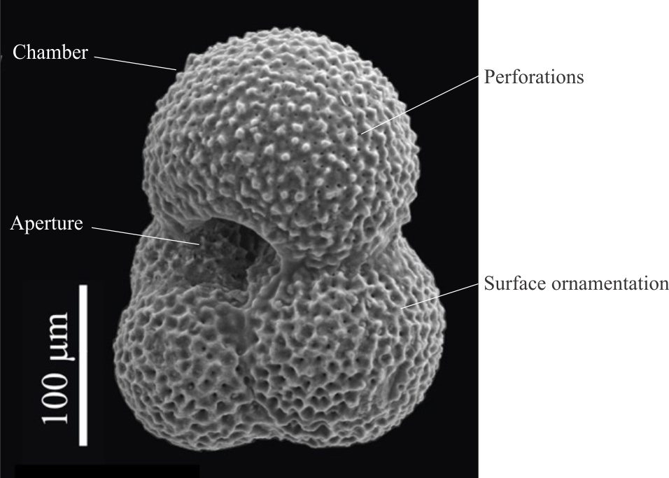
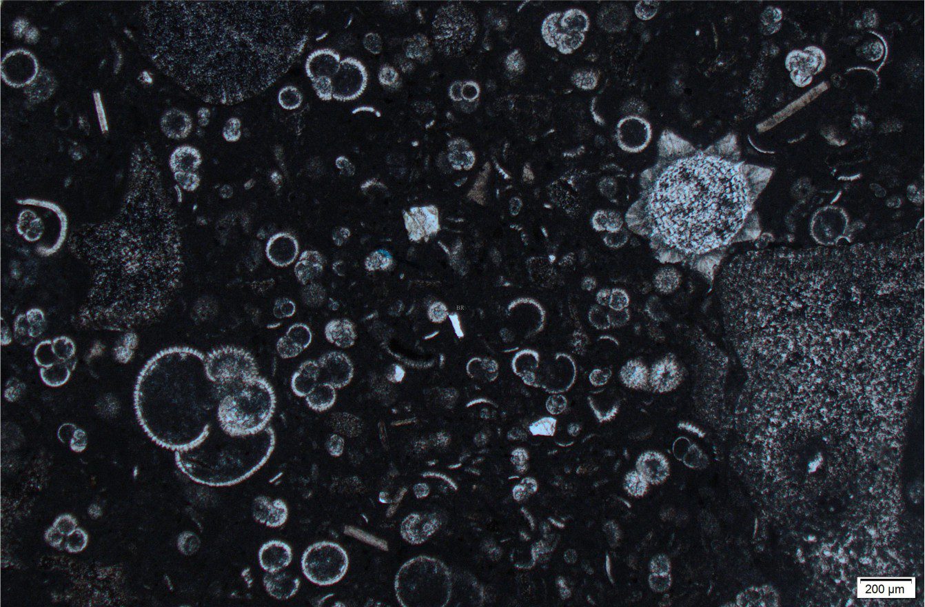
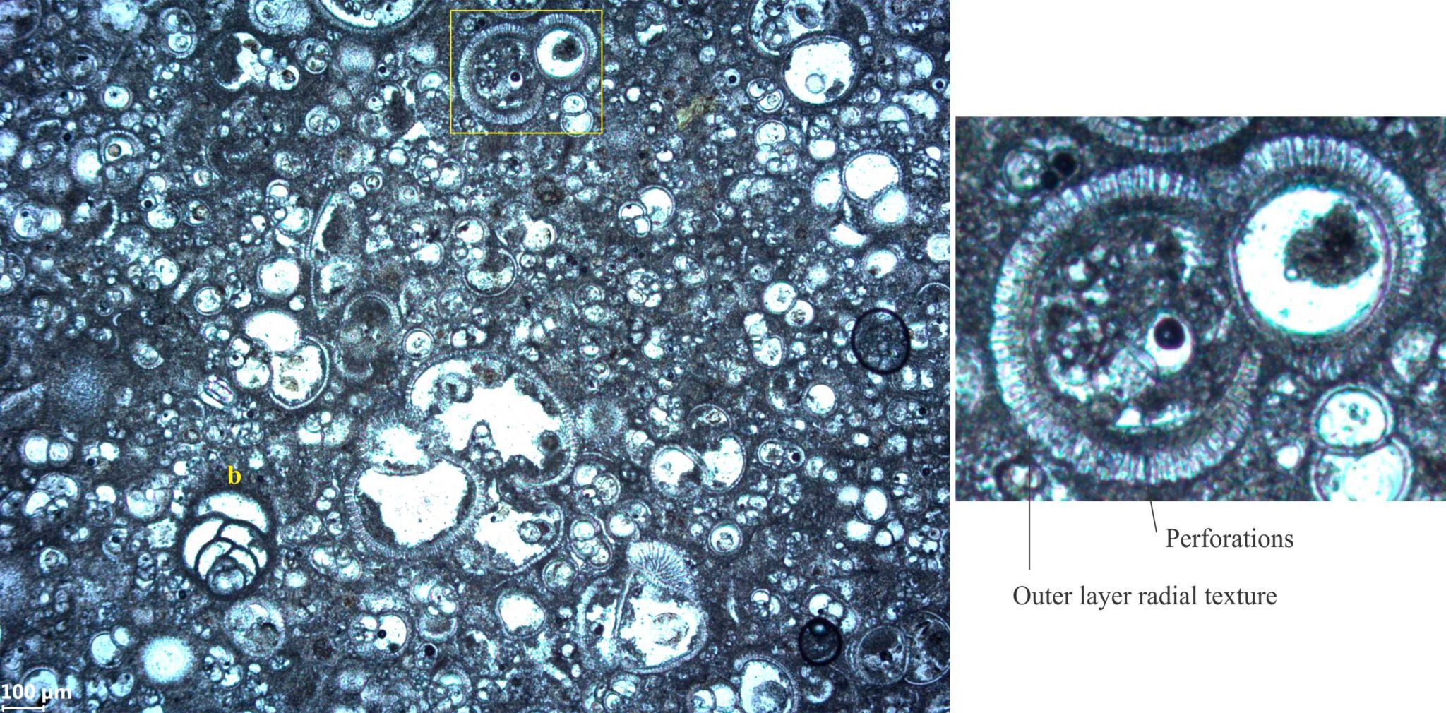
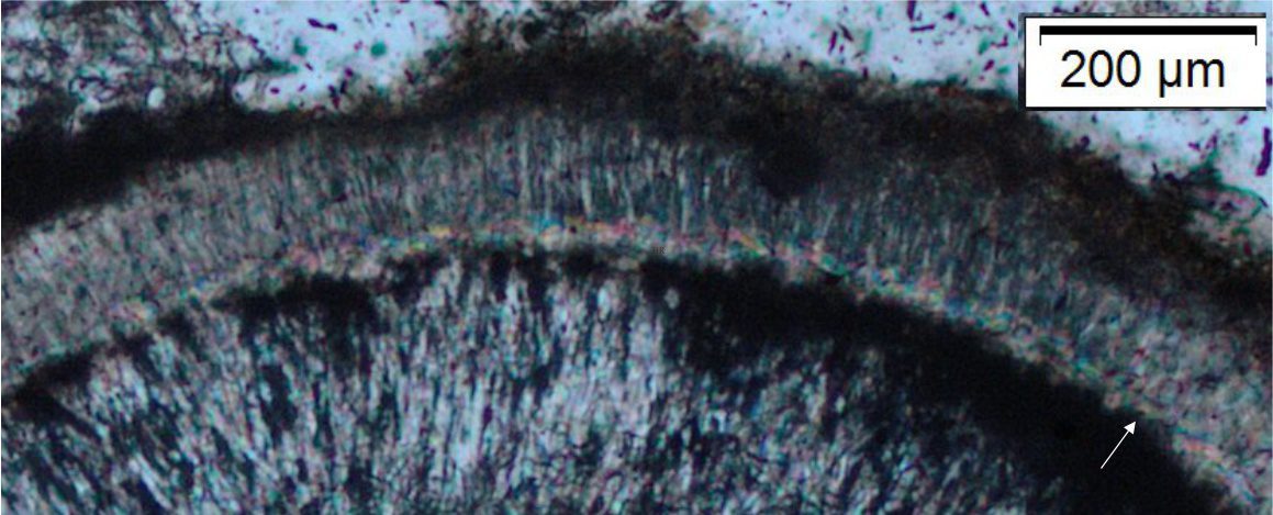
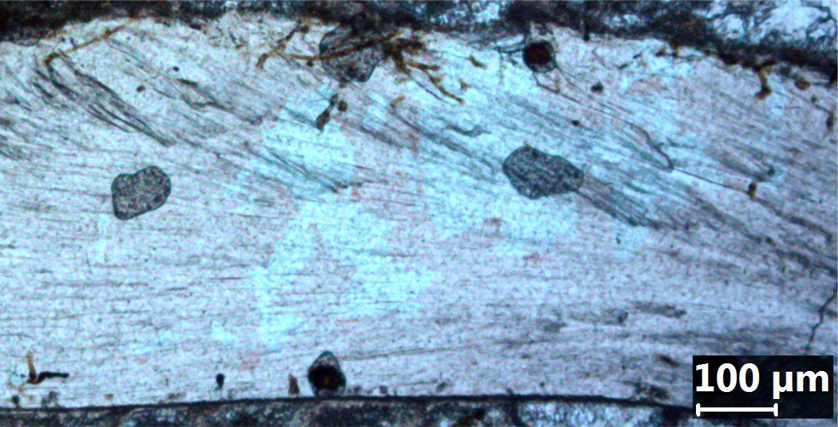
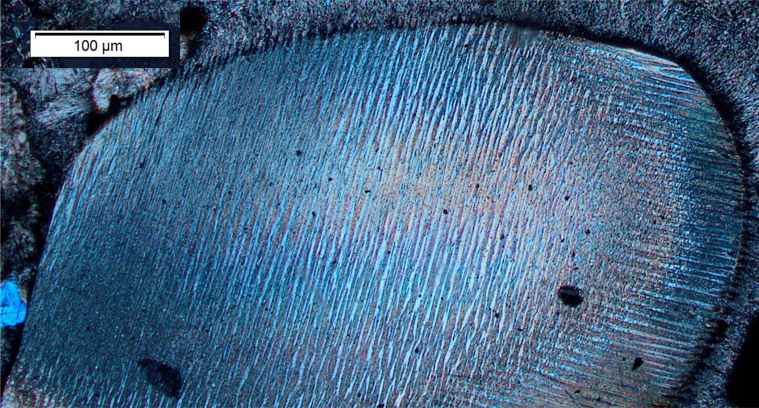
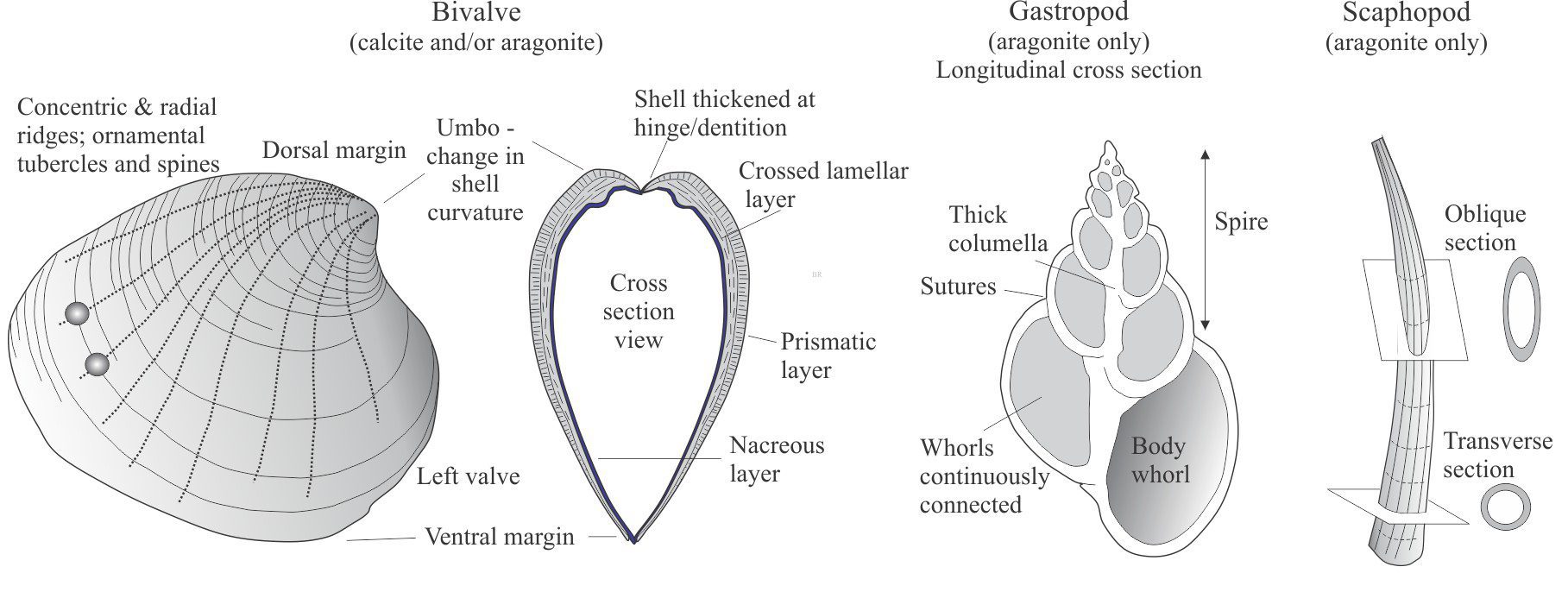
- Biological mediation of precipitation at Earth’s surface, for example aragonite in seawater whitings, ooids, and microbialites.
- Kinetic factors that determine the rate of chemical reactions and crystal formation (precipitation). A classic, and still problematic example in sedimentary geology is the precipitation of dolomite.
Crystallography was in its infancy in the late 18th and early 19th centuries. An important advancement at this time by Christian Weiss (1780 – 1856) was the recognition that crystals could be thought of as collections of similar planes arranged symmetrically around three axes. Weiss devised the three-axis system a, b, c, and determined that any single crystal face will intersect one, two or all three axes. Other faces of the same crystal could then be described according to the proportions of their intersections with the three axes.
William Hallowes Miller (1801-1880) took this a step further. Miller was a Welsh mineralogist who eventually assumed the role of Professor of Mineralogy at Cambridge University (replacing William Whewell). His contribution, published in A Treatise on Crystallography (1834), applied spherical trigonometry to a numerical system of crystal nomenclature; Millers systematic approach stands today.
Crystal axes, crystal systems, and crystal face intersections
Definition of the seven crystal systems is based on the relative lengths of the axes (labelled a, b, c) and their angular relationships. Five systems have three axes and two have four axes (hexagonal, trigonal):
- Isometric; a = b = c, all at 90o. This class has the greatest degree of symmetry.
- Tetragonal: a1 = a2 ≠ c, all at 90o.
- Orthorhombic: a ≠ b ≠ c, all at 90o.
- Monoclinic: a ≠ b ≠ c, ab = bc = 90o, ac ≠ 90o.
- Triclinic: a ≠ b ≠ c, ac ≠ bc ≠ ab ≠ 90o.
- Hexagonal: a1 = a2 = a3 at 120 o, ≠ c at 90o. One 6-fold axis of symmetry.
- Trigonal: a1 = a2 = a3 at 120 o, ≠ c at 90o. One 3-fold axis of symmetry.
Note that we label each axis according to whether it is positive or negative; by convention, the negative labels place the minus sign above the letter.
Eighteenth and 19th C crystallographers did not have the luxury of X-ray radiography to identify unit cells. Instead, they described crystal forms by measuring the interfacial angles of real crystals and determining their relative intersections with the crystal axes. The phrase ‘relative length’ is important; identification of a class does not depend on some standard axial length or crystal size. This also means that the intersection of a crystal face with any of the axes will also be relative; if a face moves parallel to itself, the relative intersections will remain the same. Every crystal face will intersect one, two or three axes.
Christian Weiss crystal face parameters
The crystal face labeling system Christian Weiss devised was based on the relative axis intersections determined by measuring interfacial angles. If we are to describe all faces comprising a crystal, we need a standard face against which all other faces are measured. The intersections on this standard face are assumed to have a value of one.
Intersection with one axis
For crystals having faces that intersect only one axis, the intersection value is assigned 1; intersections on the other two axes are at infinity. For example, if the face intersects the c axis it will be labelled ∞a, ∞b, 1c. (∞ means intersection of an axis at infinity).
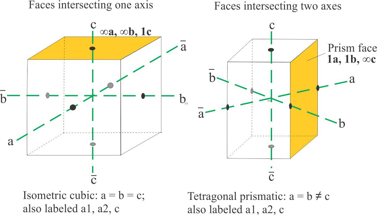
Examples of crystal faces intersecting one and two axes. The isometric system crystal is a cube of equal sides and equal axis intersections (left). The prism is another common crystal form that in this case intersects two axes.
Intersection with two axes
Likewise, for crystals with faces intersecting two axes, one of the faces is assigned the value 1, and the other will be a fraction (or multiple) of one. The third axis intersection is infinity. In the example shown below, the prism face notation is 1a, 1b, ∞c.
Intersection with three axes
Faces having three intersections are treated in the same way, but in this case the largest face on any crystal that intersects all three axes (not necessarily the largest face on the crystal) is chosen as the unit face. The intersections are all given a value of unity, so that the unit face can be described as 1a, 1b, 1c. All other faces in the same crystal can now be described with reference to the unit face.
The orthorhombic crystal shown here consists of a prism and two sets of pyramid terminations (each set is a mirror image). All faces in the pyramids intersect the three axes, but the faces on the middle pyramid are the largest so we assign one of these as the unit face. The values of the three intersections on the unit face are 1, so the face is labelled 1a, 1b, 1c.
With the unit face as our standard for this crystal, we can now tackle the other faces. Note that the actual intersection point may need to be extrapolated. For the small set of pyramid faces the intersections with ‘a’ and ‘b’ are extrapolated – their (approximate) values relative to the unit face are indicated. Thus, the face can be labelled 2a, 2b, 2/3c. Because these values are relative, we can divide by 2, so that the terminal pyramid face can be assigned 1a, 1b, 1/3c.
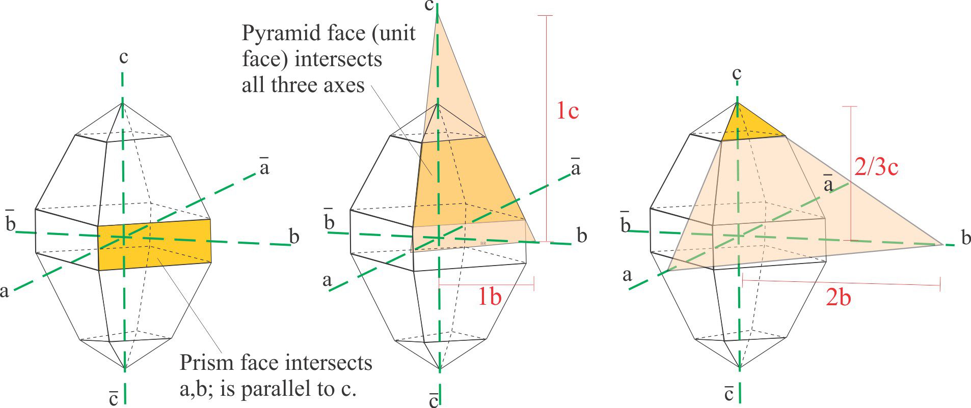
A schematic of crystal face intersections with two and three axes in an orthorhombic crystal, from which Weiss intersection ratios and Miller indices are calculated. The unit face is the large pyramid face that intersects all three axes (diagram centre).
William Miller intercedes
Weiss’ method is certainly workable, but it is regarded as cumbersome. Miller’s modification was quite simple, a simplicity that has survived. It has four parts:
- Identify the Weiss parameters for each face.
- Determine the reciprocal for each axis value.
- Normalize the values so that each face is described by integers only (i.e., clear the fractions).
- The axes are always described in the order a, b, and c; therefore, the label can omit these. Convention also requires the Miller Indices to be enclosed in brackets.
For crystal systems with three axes, the general notation for any crystal face is (hkl).
For the examples shown above, the reciprocal of the single face intersection with the axis c becomes:
1/∞a, 1/∞b, 1/1c which simplifies to 0a, 0b, 1c, or in the Miller indices convention, (001).
For the two axis intersections (tetragonal prism), the reciprocal is 1/1a, 1/1b, 1/∞c and the Miller designation (110).
For the orthorhombic crystal, the reciprocals of the unit face intersections are 1/1a, 1/1b, 1/1c, and the Miller designation is (111); for the smaller pyramid face (113), and the prism face (110). For axis intersections that are negative, the number has a minus sign above the integer.
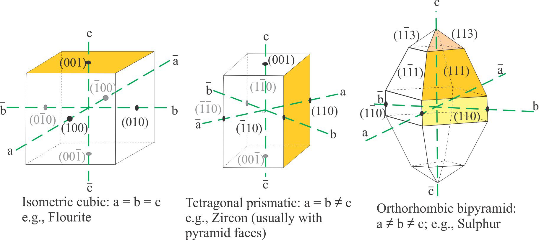
Miller indices for crystals having faces that intersect one (left), two, and three axes (right).
Miller-Bravais indices
The hexagonal/trigonal groups of crystals are the odd ones out in the crystal classification system; they have four axes, three equal axes at 120o labelled a1, a2, and a3, that are at right angles to the c axis. Trigonal crystals are frequently described in terms of hexagonal geometric properties. The general form of a hexagonal crystal face is (hkil). Quartz is the ubiquitous mineral in this group, commonly forming prisms with pyramid terminations and in some cases, bipyramids like the example shown below (this quartz habit is common in felsic volcanic rocks). Labeling hexagonal crystal faces follows the same method for both the Weiss and Miller indices.
There is an additional rule that the sum of h + k + i = 0. Prism faces that intersect two of the ‘a’ axes but not the c axis have Weiss parameters like 1a1, ∞a2, -1a3, ∞a4, and a Miller-Bravais index like (101–0). Likewise, pyramid faces that intersect two ‘a’ axes and the ‘c’ axis will have indices like (101–1) (the sum of hki is 0). For crystals having pyramid faces that intersect 3 ‘a’ axes, the middle axis intersection will be a fraction of that for the other two.
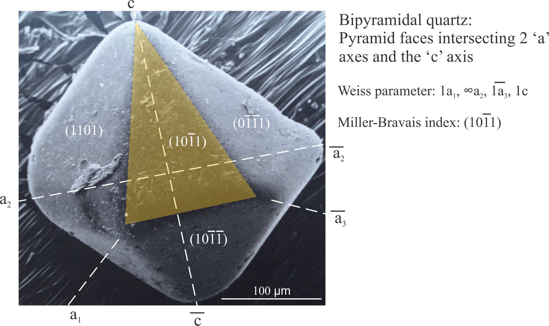
Miller-Bravais notation for pyramid faces intersecting two ‘a’ axes and the c axis in a slightly abraded grain of bipyramidal quartz (scanning electron micrograph).
Twin and cleavage planes
The Miller and Miller-Bravais notations are also applicable to the description of cleavage and twin planes because they generally parallel certain crystal faces. For example, the prominent rhombohedral cleavage in calcite is (1011), in gypsum the perfect cleavage is (010) and less perfect (100) and (111). The prominent basal cleavage in biotite and muscovite is (001) – the common form of detrital mica flakes in sediments. Albite twinning is across the (010) plane – this can also be a cleavage plane, along with (001).
A couple of good resources
Online mineralogy lectures by Prof. Stephen A. Nelson at Tulane University
Introduction to mineralogy: Tark Hamilton, Camosun College.
There are lots of YouTube presentations on the topic.
Other posts on this topic
Optical mineralogy: some terminology
Sliced thin; kaleidoscopes with a geological purpose
Sliced thin; time and process recorded in igneous rocks
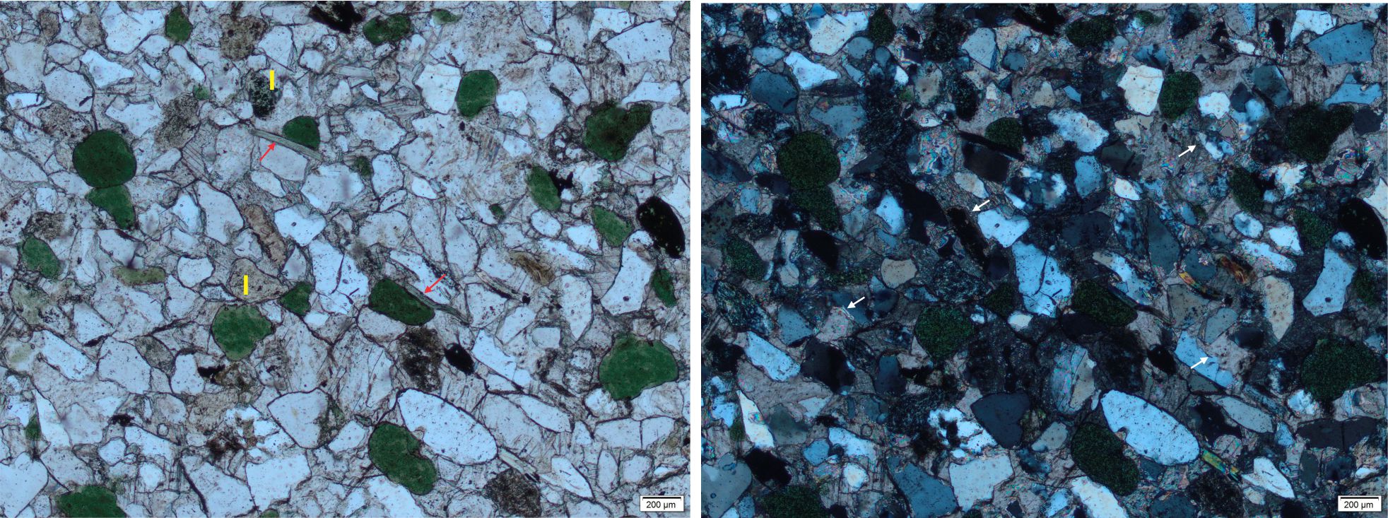
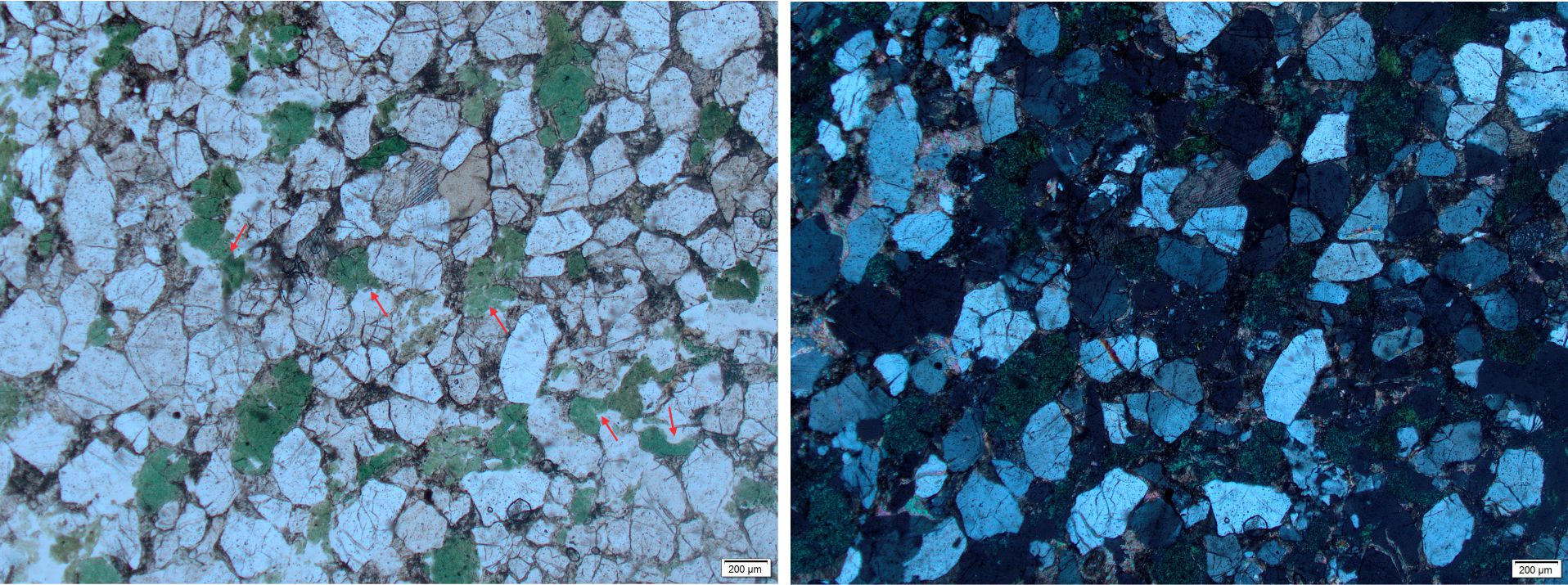
Sliced thin; the unfolding story of sandstone
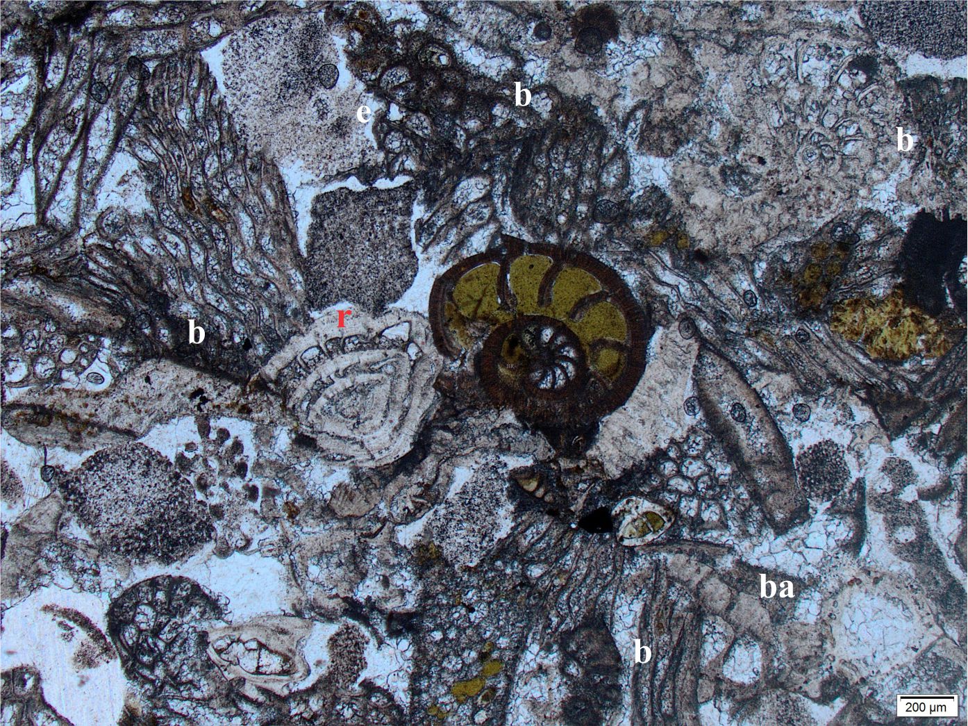
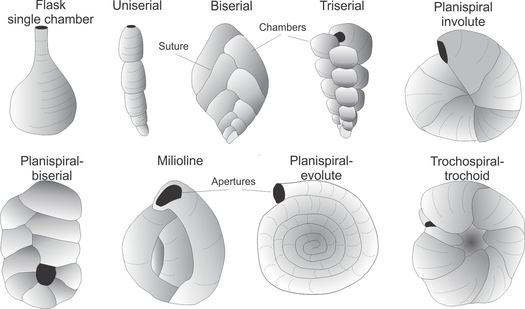
Sliced thin; the universe revealed in microfossils