At home

Image of the day/week/month

The sartorial spendour of spiny Murex – the real show-offs in the world of gastropods. From the left: Chicoreus ramosus (the Ramose Murex, Philippines); Murex pecten (Venus comb Murex, Philippines); Porieria zelandica (New Zealand) – the one I stood on!.

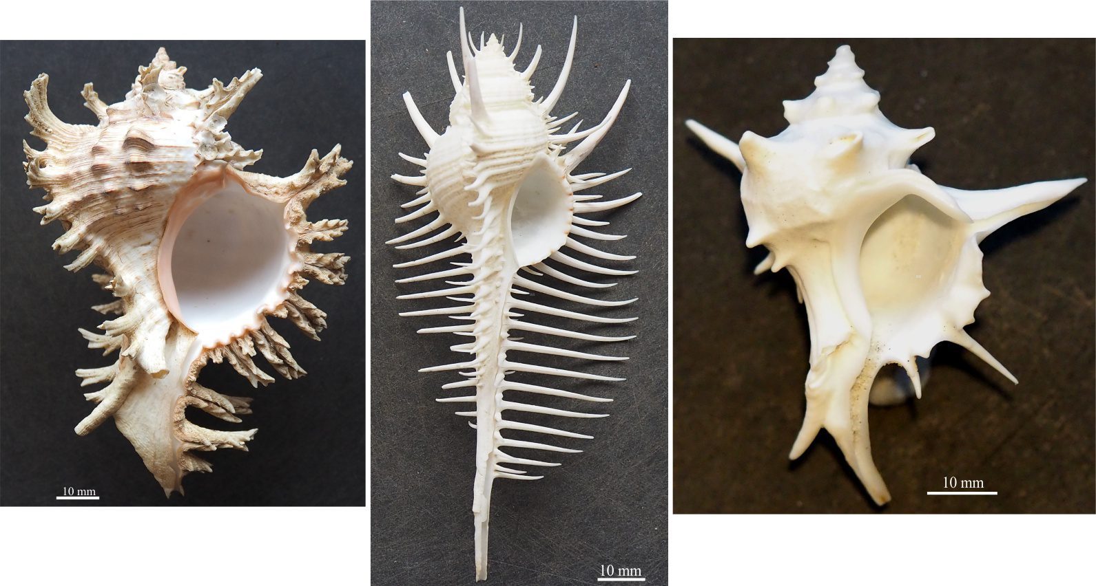
The sartorial splendour of spiny Murex – the real show-offs in the world of gastropods. From the left: Chicoreus ramosus (the Ramose Murex, Philippines); Murex pecten (Venus comb Murex, Philippines); Porieria zelandica (New Zealand) – the one I stood on!.

374 articles, atlases, and glossaries to choose from

Herein you will find posts on Earth and planetary sciences, Art and Science and other digressions that focus on Science Communication and online resources for students of all disciplines, but particularly Geology.  Post categories-topics are linked to the navigation bar or just head to the latest additions listed below.

I do this for the love of it. I do not receive any remuneration for the site (and I don’t advertise). The website (geological-digressions.com) is not attached or beholden to any organization.

A number of colleagues have kindly donated images for certain categories of posts. They are all acknowledged, usually in the caption to an image. They are also acknowledged in a Contributors Page.

The How to…   articles are designed for geology students, providing outlines of method and theory for some of the basic tasks that geologists undertake in the field and lab. They are directed primarily at beginning and undergraduate geology students and anyone else wanting a reminder or primer, and as such are a bit more technical than other posts.

Peruse the Atlas series for images of different geological environments and processes, modern and ancient.

The Glossary has been compiled from terms used in this website. Links to the relevant posts are included. There are currently 11 glossaries.

And finally, if you would like to know something about me, where I’ve come from, where I’ve been – A geological life

If you use any of the images on this website, please follow the normal protocols for attribution – for example: Brian Ricketts or Geological Digressions followed by the article link/URL.

Thanks.


Latest Posts

Mohr-Coulomb failure criteria

A schematic of a typical experimental set-up for triaxial tests on rock samples. Confining pressure is increased by increasing the pressure on the oil surrounding the jacketed rock cylinder (from R. Weijermars 2023, Principles of Rock Mechanics, Figure 6.11b. Creative Commons Attribution-NonCommercial-ShareAlike 4.0 International License. PDF available). The example of sheared rock shows fracture planes that are highly irregular, plus subordinate microfractures. Typical stress-strain curves (right) are shown for increasing confining pressures; differential stress is the principal maximum stress σ1 minus the minimum stress σ3. The steep part of each curve (parallel to the green line) is the initial, recoverable elastic response; beyond this limit the curves represent permanent deformation. From Middleton and Wilcock 1974, Figure 4.8.

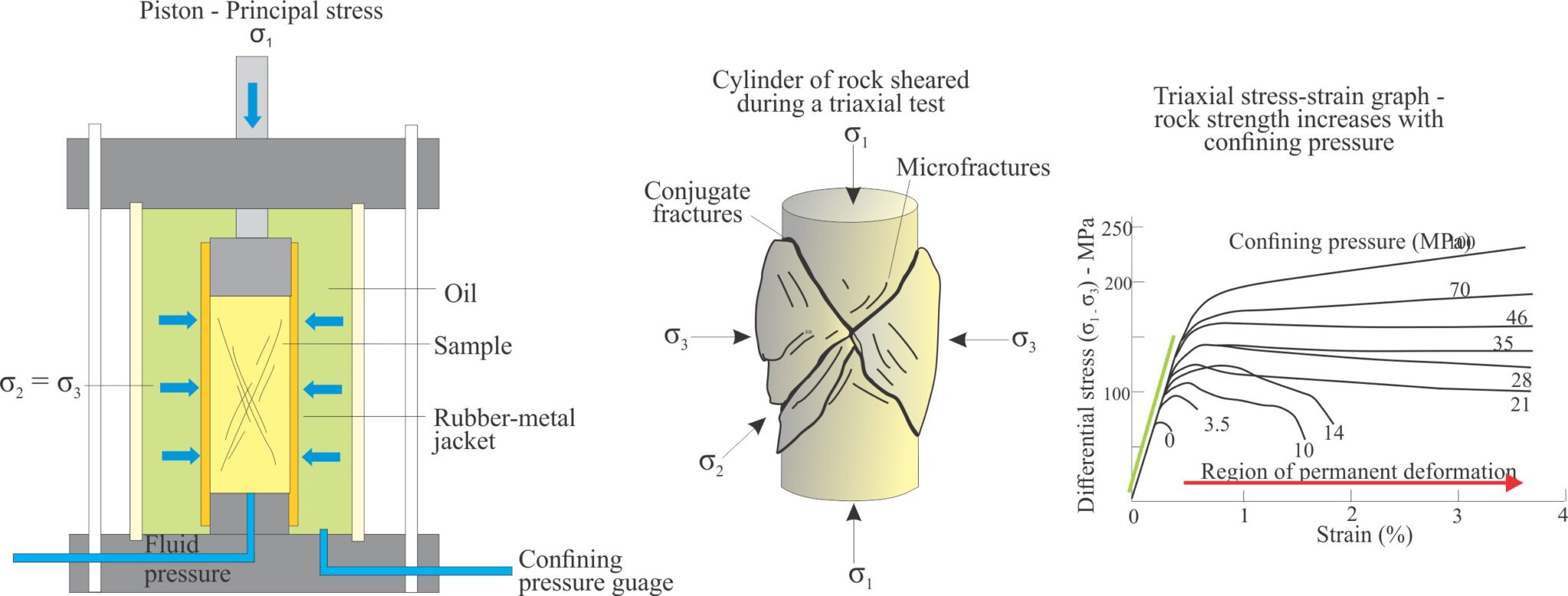
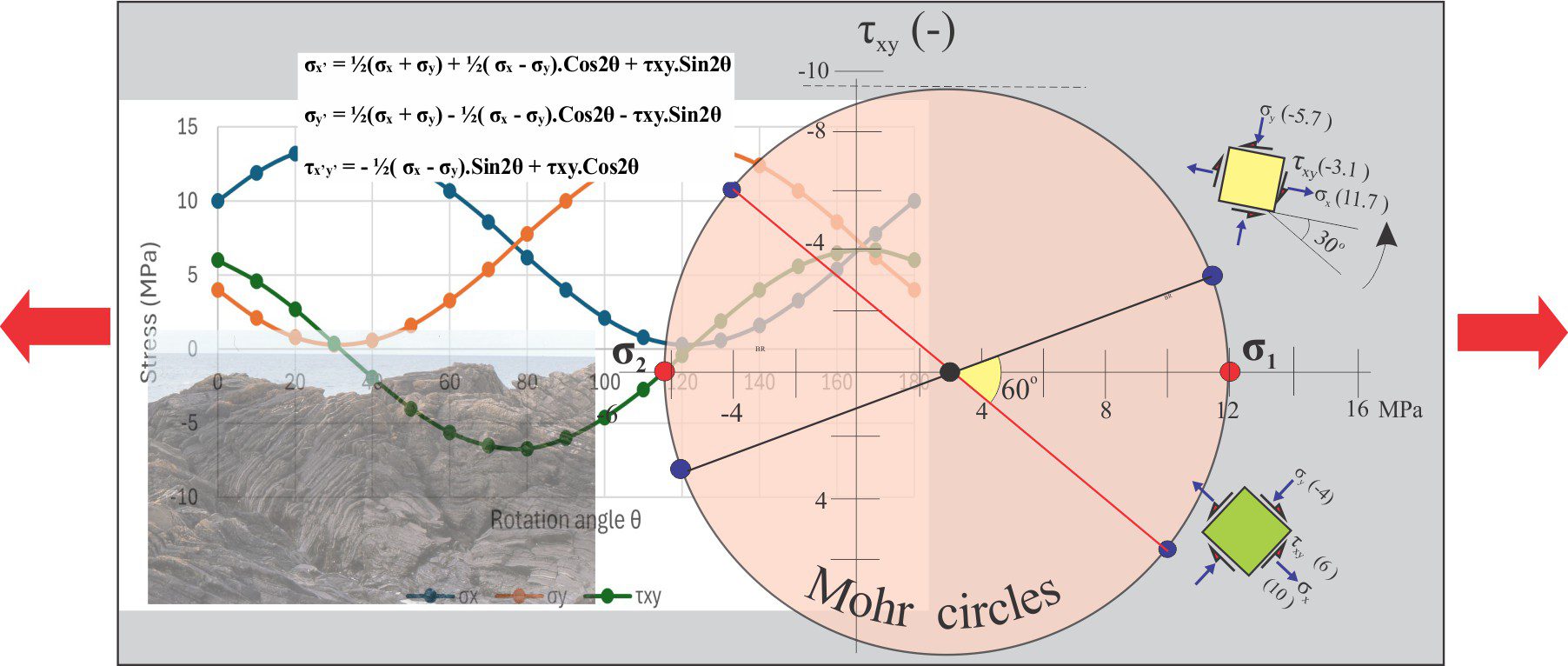
Mohr circles and stress transformation

A montage of stress transformation paraphernalia and rock deformation

Strike-slip analogue models

Sketch showing the topographic surface at the end of restraining bend deformation after 10 cm of pure strike-slip base plate displacement. The initial stepover angle was 30o. Resulting strain has been partitioned into several oblique slip, reverse faults – the strike-slip component of displacement is the same sense as the PDZs (sinistral). Larger faults are mechanically linked to the PDZs. The main part of the antiformal pop-up structure has been rotated 6o counterclockwise. Layering depicted in the two cross-sections has been simplified from the published examples. The faults form a characteristic positive flower structure close to the left PDZ and are more fan-shaped in the antiform popup centre. Both diagrams redrawn from McClay and Bonora, 2001 op cit., Figures 3e and 4.

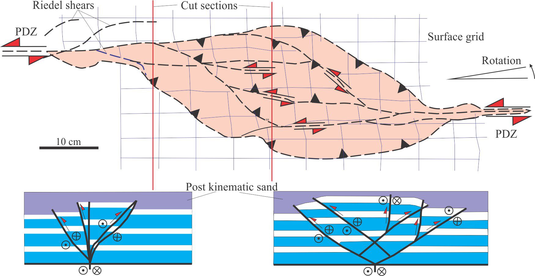
Analogue models of faults: scaling the materials

Scaled sand-box experiments are an ideal medium to observe rock deformation that, in this example, involves synkinematic deposition during rift-like crustal extension. The choice of model materials, in addition to imposed boundary conditions such as strain rates, will determine the outcome of the experiment. Dry sand was chosen for this model because its brittle behaviour under the model conditions is a good representation of natural rock failure. Diagram modified slightly from Eisenstadt and Sims, 2005, Figure 3a.


Geological models: An introduction

Model dimensions and dimensional analysis

Analogue models

A sand-box size analogue model of thrust-fault propagation folds in layered stratigraphy, at 44% horizontal shortening. A new, embryonic thrust is forming at the frontal edge of the “thrust belt”. These experiments, although not fully scaled geometrically or dynamically, retain considerable heuristic value for students. The image was generously provided by Prof. Sandra McLaren, Melbourne University.

Beds and bedding planes

Parallel bedding in a Paleocene turbidite succession, Point San Pedro, California. The thickness of individual beds varies little along their lateral extent, at least within the confines of the outcrop; our view of bedding planes is limited to their 2D extent. The thickest bed is about 50 cm.

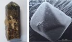
Miller Indices in crystallography

Minerals are defined by their chemical composition and their crystal forms. Miller, and Miller-Bravais indices are the standard where every face on a crystal is given a unique description that in general notation are written as (hkl) and (hkil). Two of the most common forms are prisms (the tourmaline crystal on the left), and pyramids as shown in the tourmaline crystal termination and the volcanic quartz.


Salt marsh lithofacies

A 45 cm thick, salt-marsh cliff section reveals stacked marsh-aggradation episodes. Each episode is bound by a thin, dark brown carbonaceous band (white arrows); for each episode the overlying marsh deposits consist of clay and silt. Each episode contains root structures that penetrate the deposits of earlier deposits (e.g., yellow arrow). Larger wood fragments were probably derived from nearby coastal shrubs and trees. Coin (lower right) is 24 mm diameter. Bay of Fundy, Nova Scotia (same locality as shown in the image at top of the page).

Mangrove ecosystems

Mangrove lithofacies

Mangroves dominate this estuarine channel-tidal flat system. The channel is mud-bound, about 1.5 m to 2 m deep and 5 m to 6 m wide, with margins stabilised by the tangle of roots. Tidal flood waters cover the vegetated flats to depths of only a few centimetres. Each tidal cycle replenishes the supply of food and nutrients to the vegetation and the local invertebrate fauna. Whitford estuary, south Auckland.

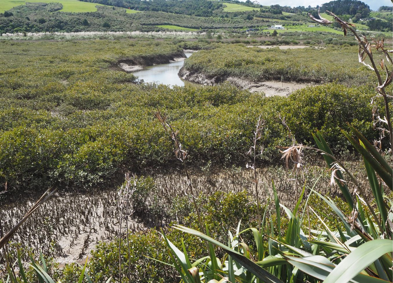
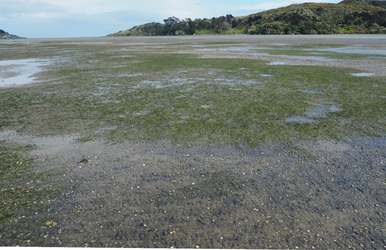
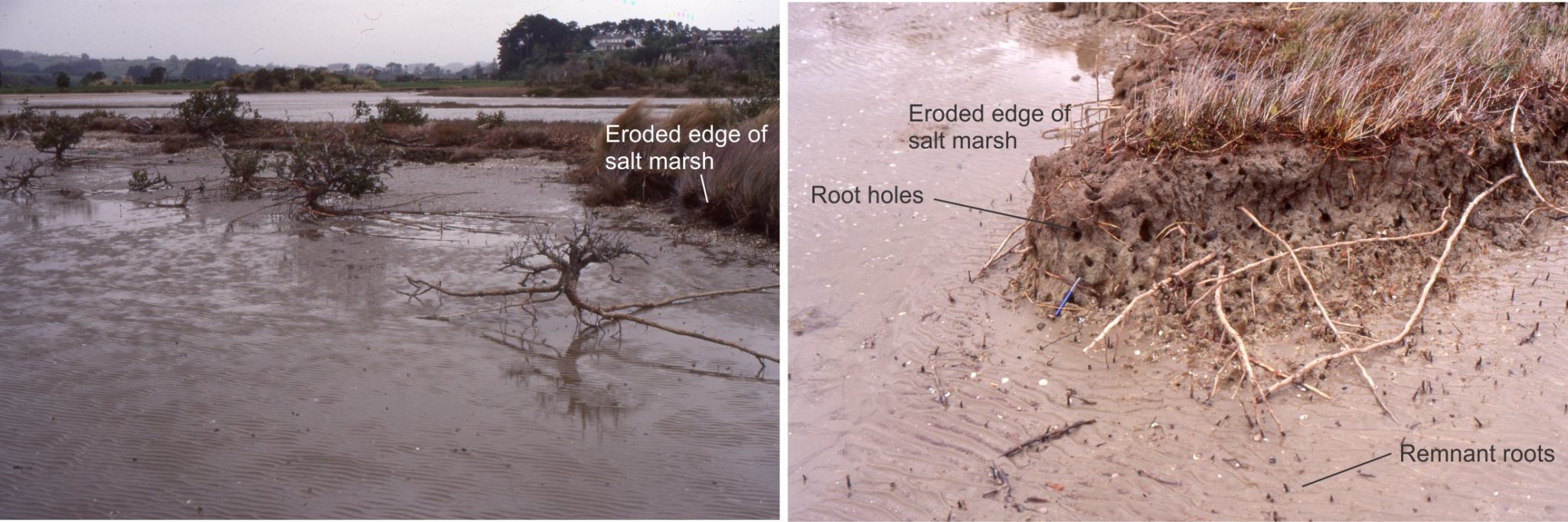
Seagrass lithofacies in the rock record

Part of a Zostera marina meadow on sandy tidal flats, Savory Island, British Columbia. Mud content here is

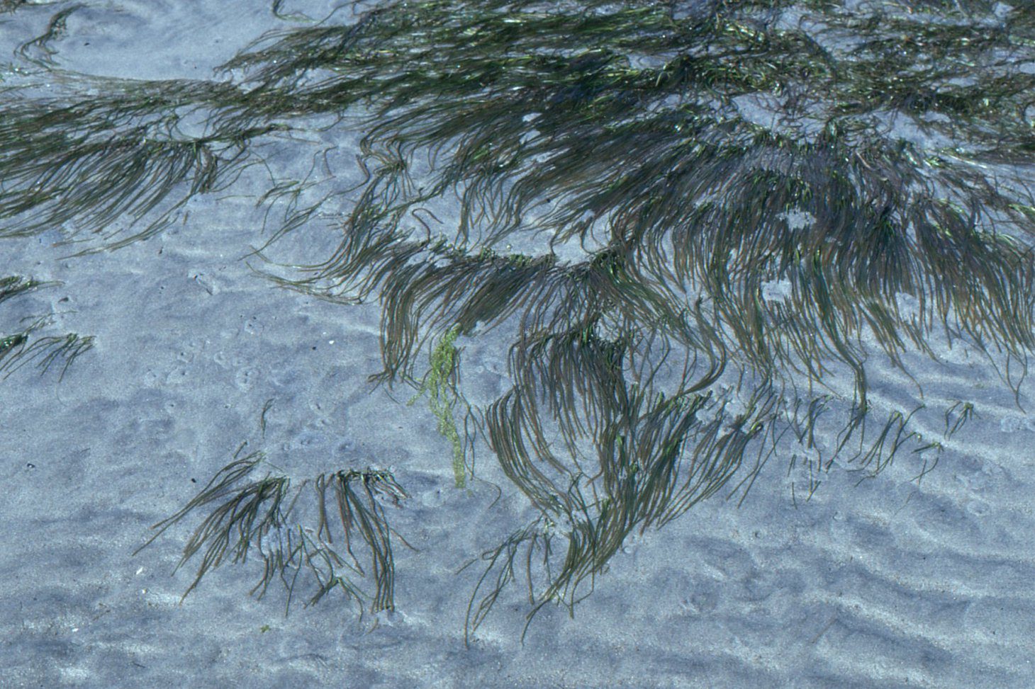
Seagrass meadows and ecosystems

Meadows of the seagrass Zostera muelleri exposed at low tide on tidal flats, Raglan Harbour (west coast, New Zealand). They extend into the adjacent subtidal channel. The substrate is fine-grained sand with 10-20% mud. The surface is littered with the shells of the bivalve venerid Austrovenus stutchburyi, a few Macomona liliana (a Tellinid bivalve), and scavenging gastropods. Meadow coverage in this view is a few hundred square metres.

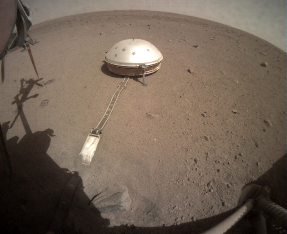
Marsquakes: The InSight experiment

InSight’s seismometer (SEIS) was deployed by a robotic arm to sit directly on the martian regolith. The robotic arm covered the tether with a layer of loose soil to protect it from wind-blown sand and to minimize acoustic noise. The dome also acted as a shield against wind and thermal effects. Dome top is about 80 cm high. SEIS weighed 29.5 kg.

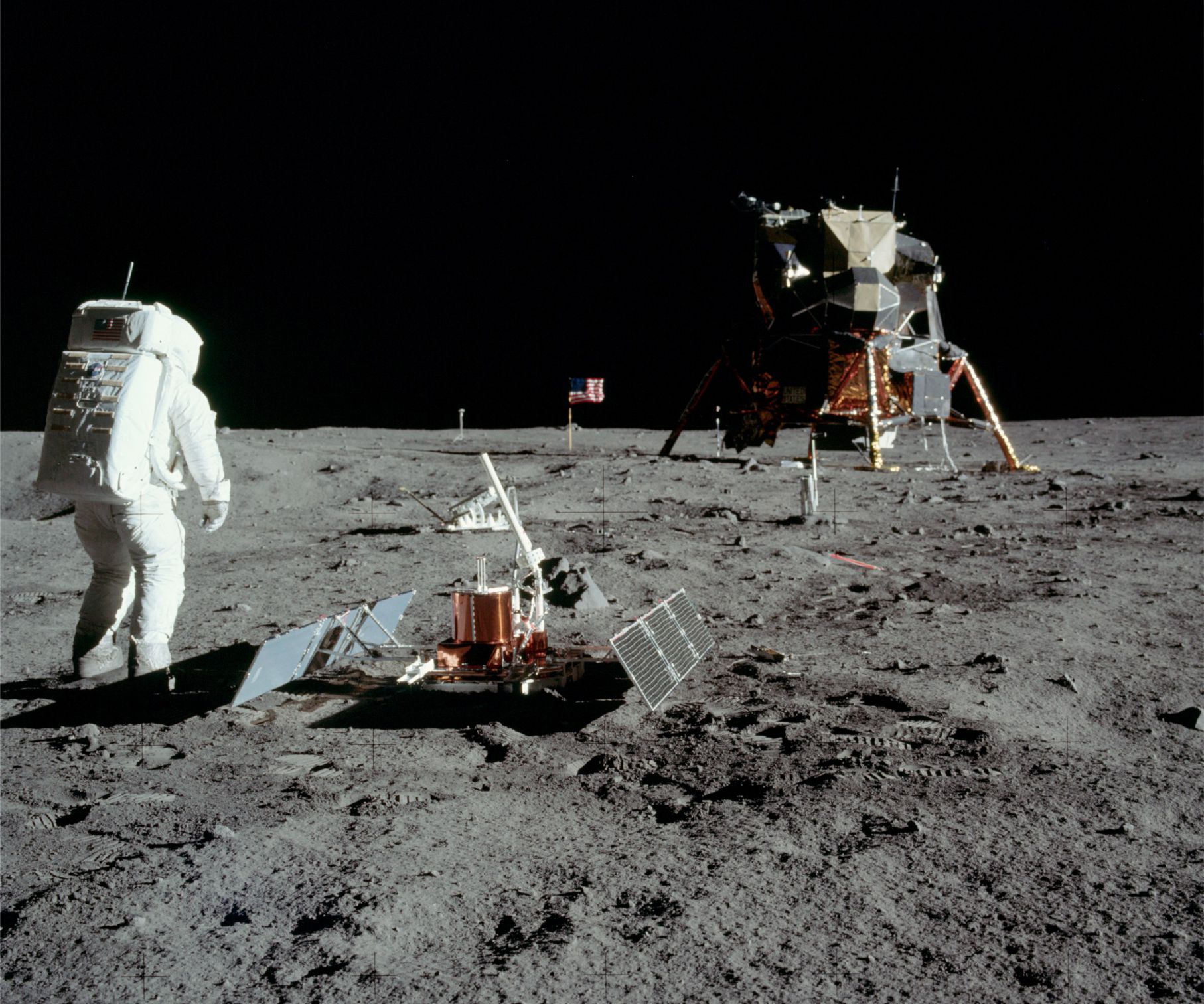
Seismic experiments and moonquakes

The first seismometer to be installed on a planetary body other than Earth, was at the Apollo 11 landing site on Mare Tranquillitatis. The passive seismic experiment lasted about 3 weeks. Here, astronaut Buzz Aldrin has deployed two solar panels and antenna. Several boot impressions are visible in the soft regolith soil. Image credit: NASA

Graded-bedding lithofacies

Controlled experiments on turbidity currents allow us to observe the dynamics of flows and the organization of their deposits. Phillip Kuenen and Carlo Migliorini (1950) conducted experiments like the one shown here – they were able to reproduce the kind of graded bedding observed in many outcrops, setting in motion a scientific rethinking of deep-sea sedimentary processes that still resonates today. The experimental flow shown above was designed to sample the concentration of sediment suspended in the turbulent plume over the duration of the flow (using siphons). Four time-lapse images show different stages of flow development, with two of the siphons at 8 m and 11.6 m from the flume inlet. The inset curve plots flow velocity with distance along the flow path. Image credit: Modified slightly from O.E. Sequeiros et al., 2009. Figure 5, Experimental study on self-accelerating turbidity currents. J Geophysical Research; Oceans

Three posts on tempestites:

3 Evolving tempestite lithofacies models

2 Storm surges and tempestites

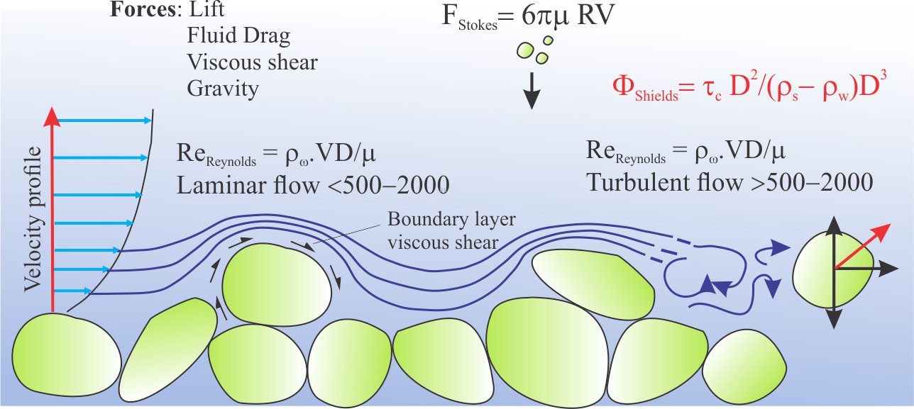
1 Storms and storm surges: Forces at play

Erosion of unconsolidated coastal dune sands by storm surges driven by cyclone Gabrielle damaged building foundations and beach access ways. The artificial carapace of boulders and blocks, intended as a coastal defense, was easily dismantled by wave surges that coincided with high tide. The storm was a category 3 tropical cyclone that tracked the east coast of Aotearoa New Zealand's North Island in February 2023.

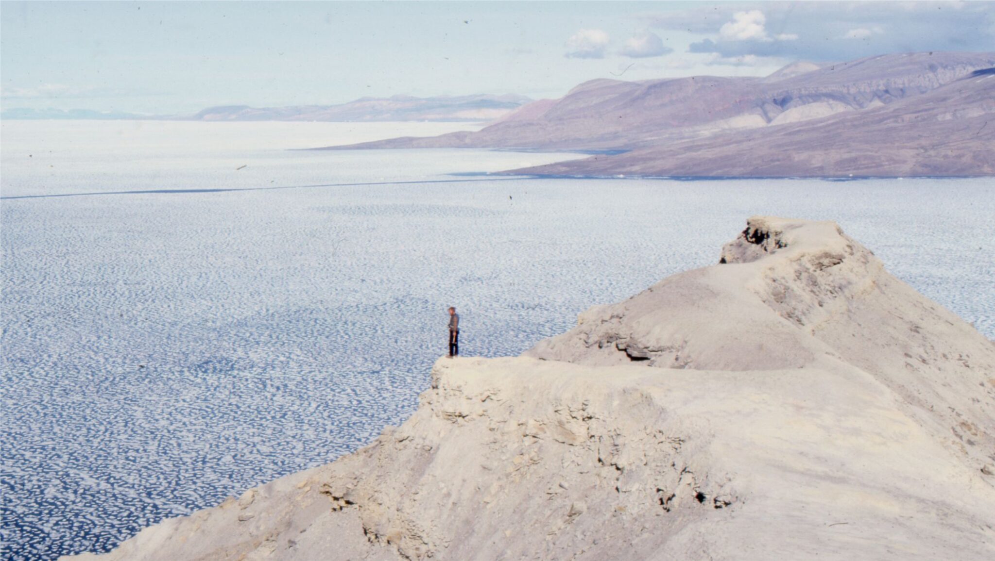
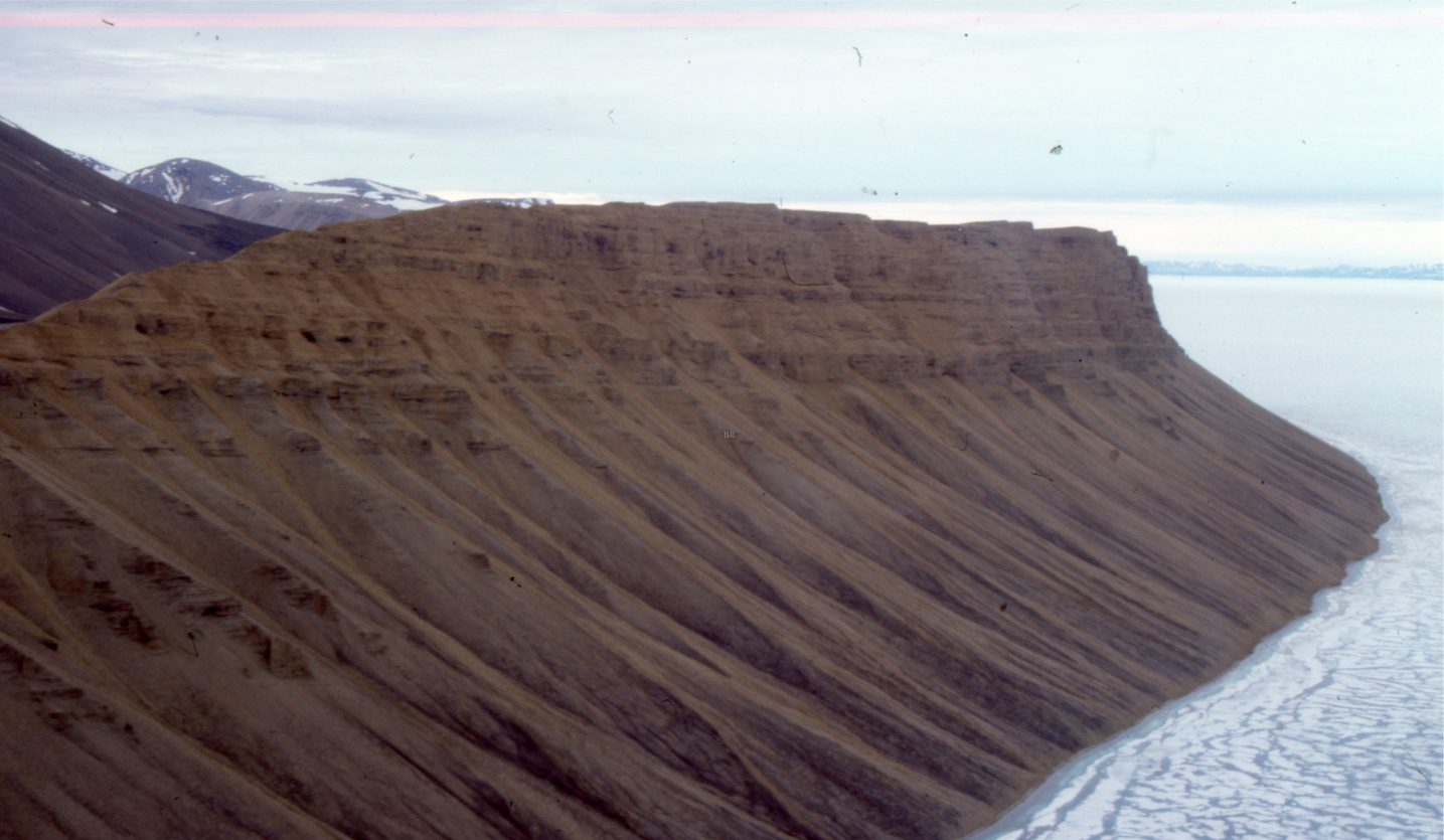
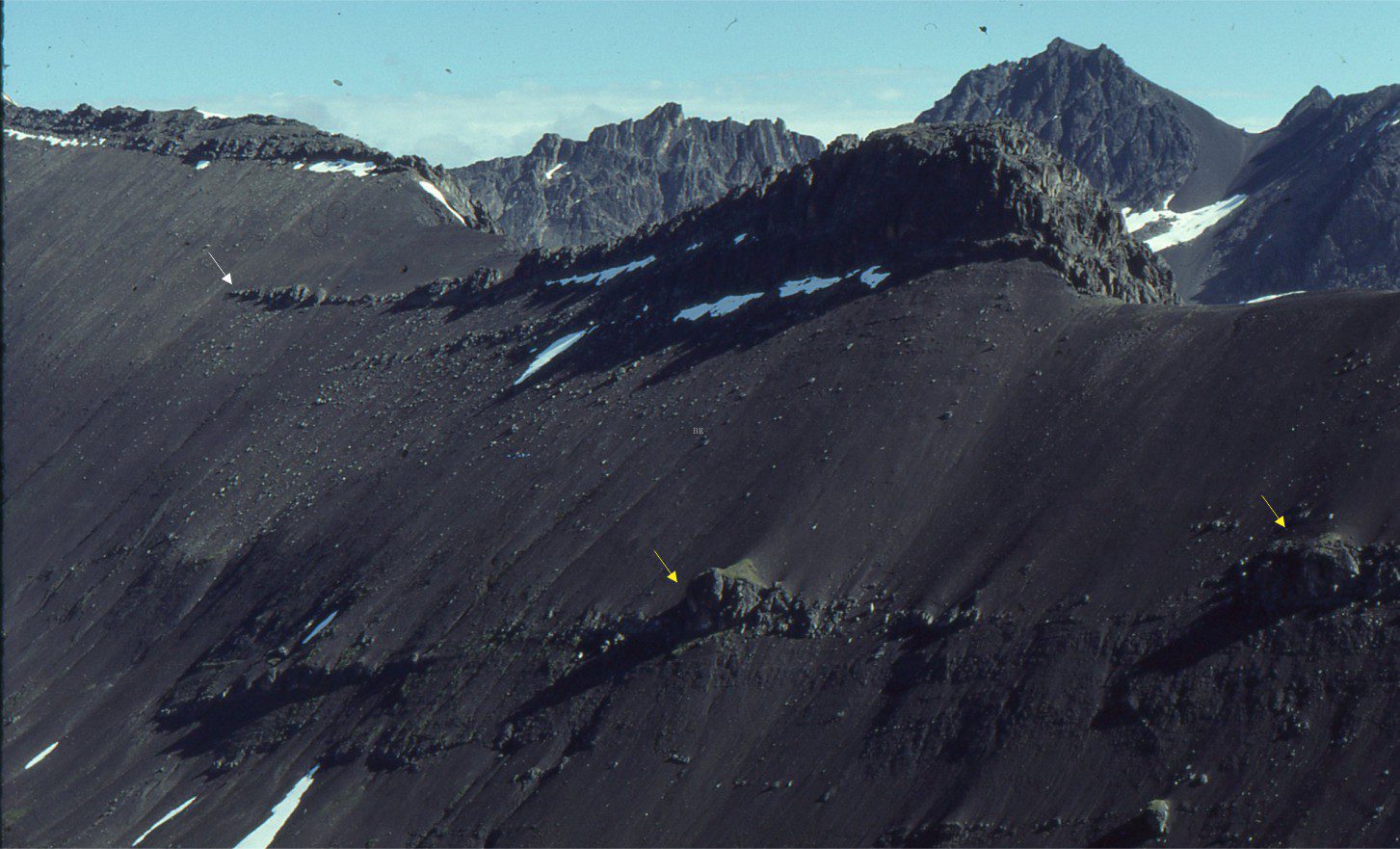
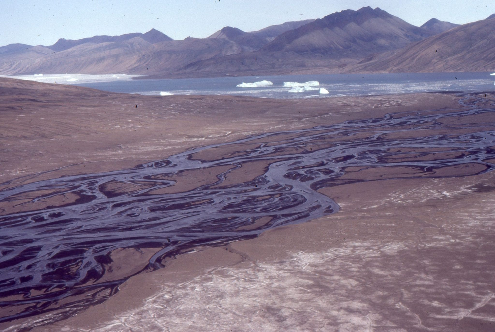
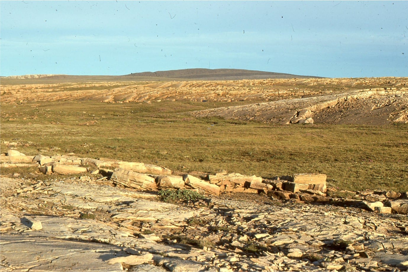
How do we identify a basin margin?

Cañon Fiord, Ellesmere Island – a small, deep, steep-sided, glacially carved Arctic basin.

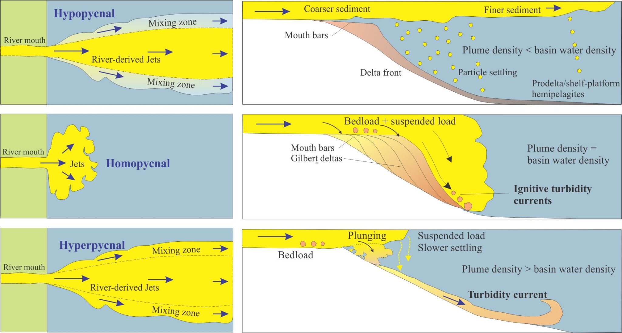
The three pycnals: Hypo-, homo-, and hyper

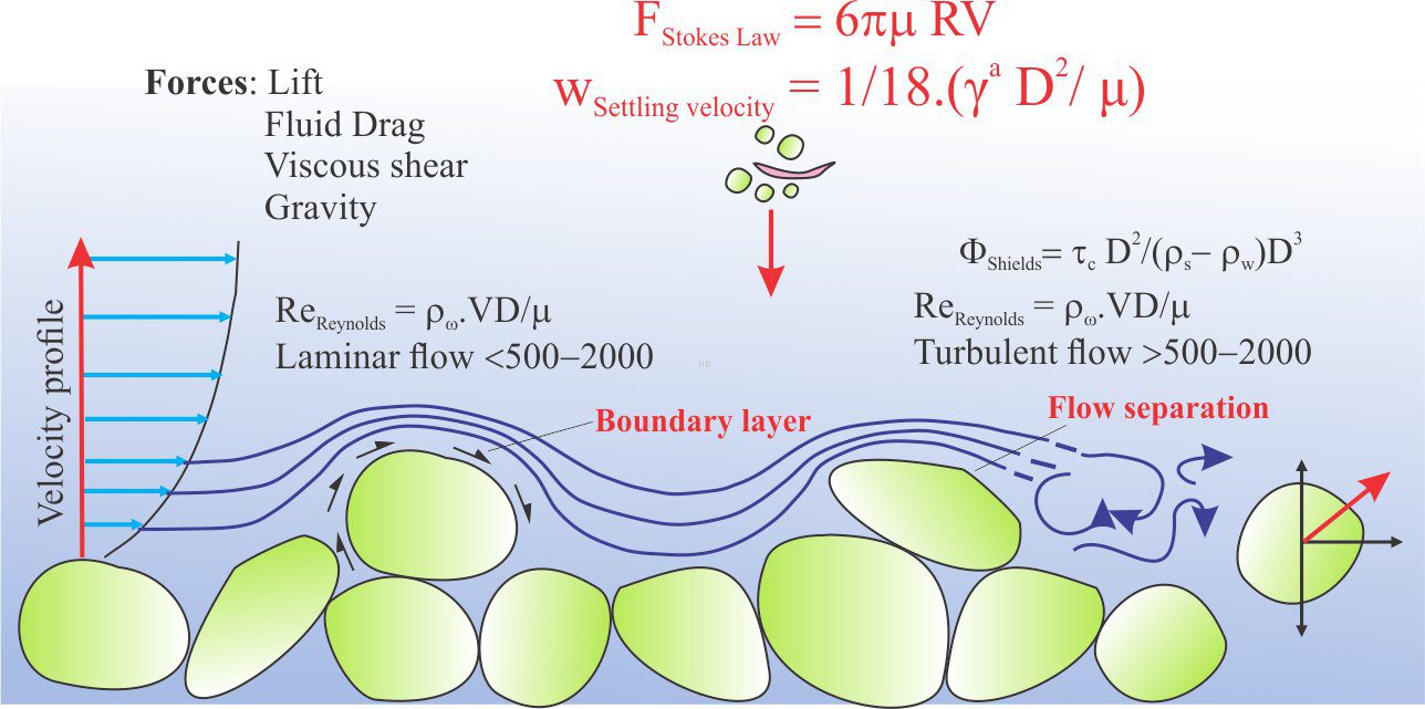
Fluid flow: Stokes Law and particle settling

Stokes Law for particle settling in a schematic context of other fluid flow functions

Fluid flow: Shields and Hjulström diagrams

A schematic portrayal of some important functions used to determine the character of fluid flow and sedimentation.

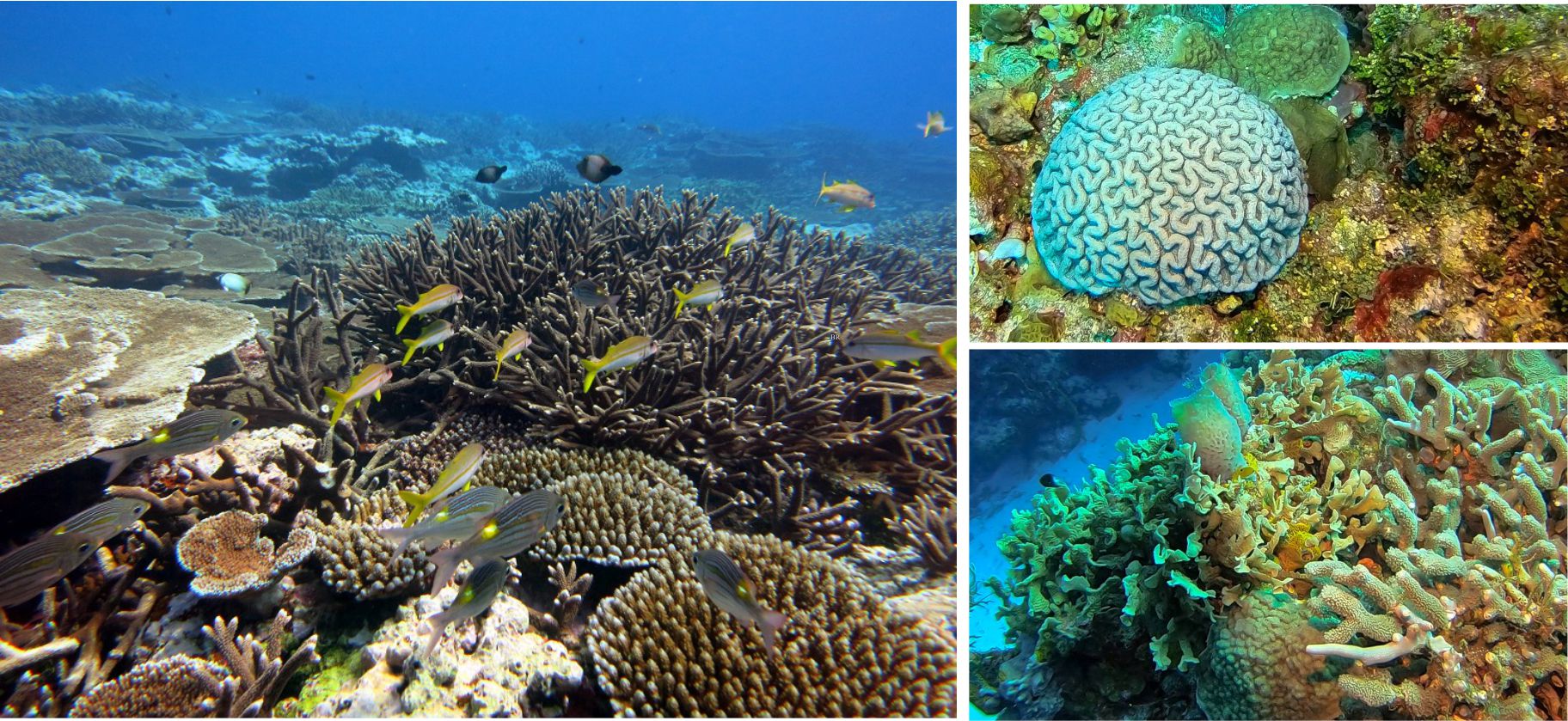
Coral morphology for sedimentologists

Modern Scleractinian coral reefs: One of the most diverse ecosystems on Earth. Descriptions and credits posted in the following text.

A geological life

Negotiating a passage through remnants of sea ice, beginning the 1977 field season on Belcher Islands.

Glossary of planetary geology

The lithofacies of colluvium

Talus fan colluvium sourced from bluffs of Eocene conglomerate (Buchanan Lake Fm.), Emma Fiord, Ellesmere Island. Depositional mechanisms are primarily mass wasting (rock fall and slide) and slope wash during the Arctic spring thaw. The transfer of colluvium to the shoreline will produce significant improvements in sorting and stratification.

Glossary: Paleontology


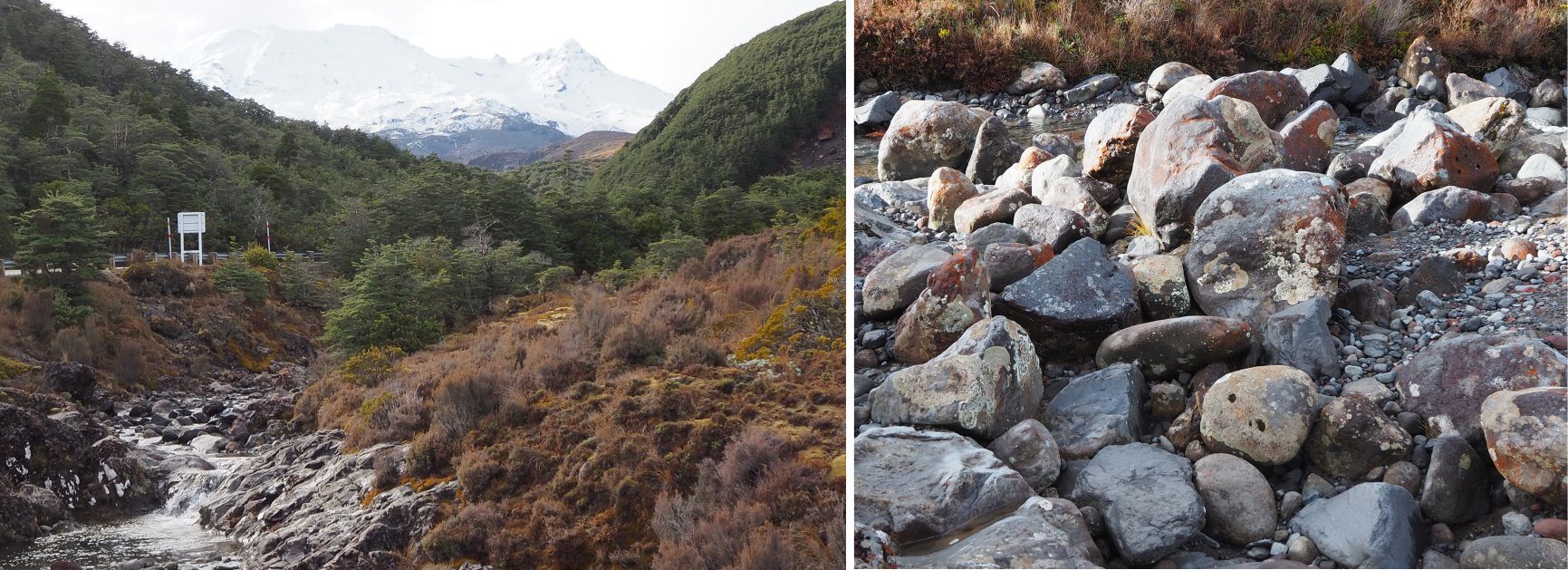
The lithofacies of mountain streams

Left: Bedrock floored boulder stream draining the outer slopes of the active volcano, Mt. Ruapehu, New Zealand. There are multiple bedrock and boulder steps and pools along its course. The channel margins are mantled by coarse- and fine-grained tephra, colluvium, and paleosols. Right: An exposed part of the active channel containing a mix of rounded and angular gravel clasts (andesite and basalt) and scattered pockets of sand. The summit is about 5 km away (line of sight), along which there are multiple bedrock (lava flows), tephra, and colluvium sources. Significant rounding of clasts can occur over that distance.

Debris flow lithofacies

A submarine channel from thalweg to overbank pinchout margin (white arrow), incised into slope mudrocks and filled by debris flow conglomerates (about 20 m thick). Lower in the succession, a couple of overbank debris-flow lobes sourced and isolated from an older channel bankfull event (yellow arrows). Mid Jurassic Bowser Basin, northern British Columbia.

Beach and shoreface gravels

Pocket beaches blanketed by pebbles, cobbles and boulders, secreted away among rocky promontories, islets, nooks and crannies. One of the many rocky coasts of north Auckland.

Crossbedded gravel lithofacies

Tabular crossbedded pebble conglomerate in scoured contact with underlying tabular crossbedded lithic sandstone. Flow in both units was to the left. The apparent dip of gravel foresets is 20-25o (dashed lines outline general trends). The lowermost conglomeratic tabular bed can be traced laterally for about 8 m. It is overlain and locally scoured by tabular and trough crossbedded conglomerate. Lower Cretaceous Elk Fm, southern Alberta.

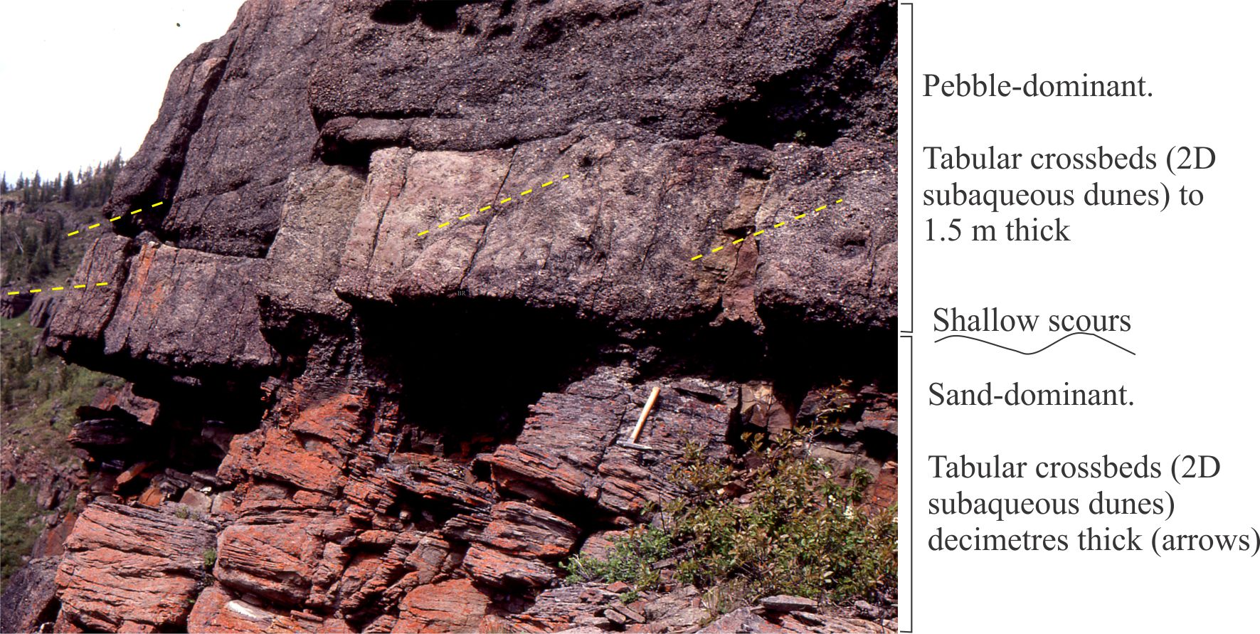
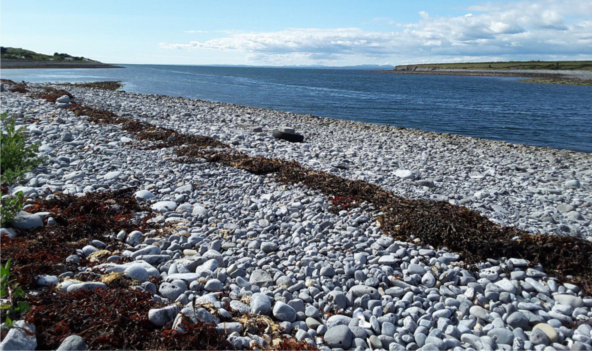
Introducing coarse-grained lithofacies

The beach next to the pub at New Quay, County Clare, Ireland, is composed of well-rounded pebbles, cobbles, and boulders that extend through the swash-backwash zone to a spring tide – storm ridge above the line of brown seaweed. Most of the clasts were sourced from local, Late Pleistocene glaciogenic deposits that in turn were derived from the nearby glacio-karsted Burrens, a glaciated terrain underlain by Carboniferous limestone.

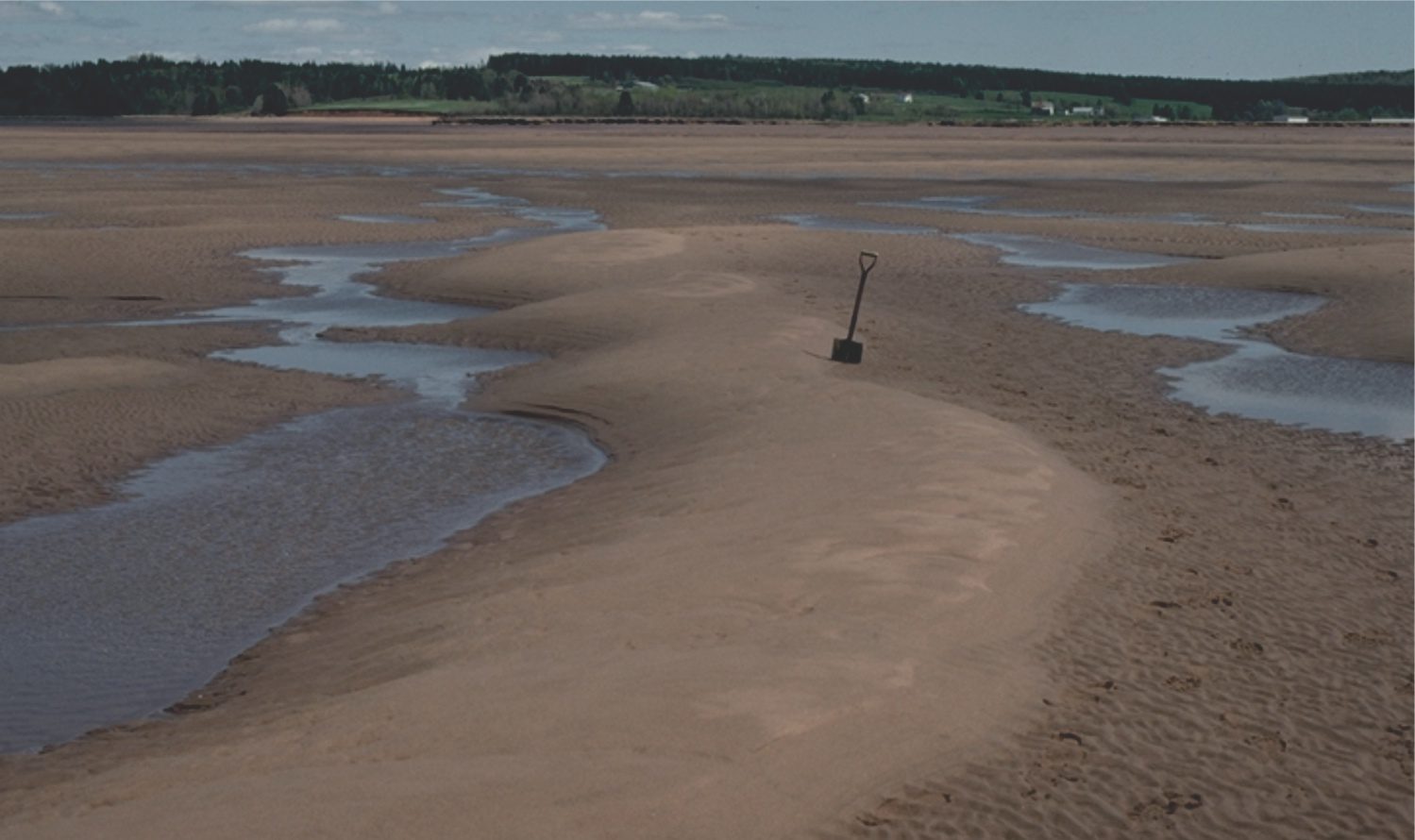
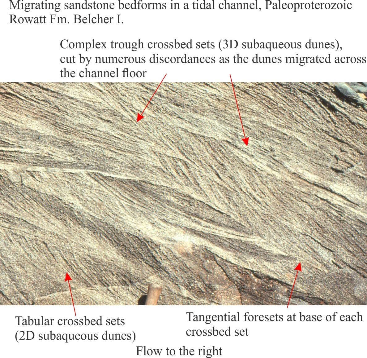
Subaqueous dunes influenced by tides

Modern intertidal dunes deposited on a flood tide and modified during the subsequent ebb flow. The spade is located at the edge of the stoss face. Erosion of the lee face during ebb tidal flow has created a subdued, rounded dune profile. Sedimentation during the next incoming tide will reactivate deposition across the lee face. Minas Basin, Bay of Fundy.

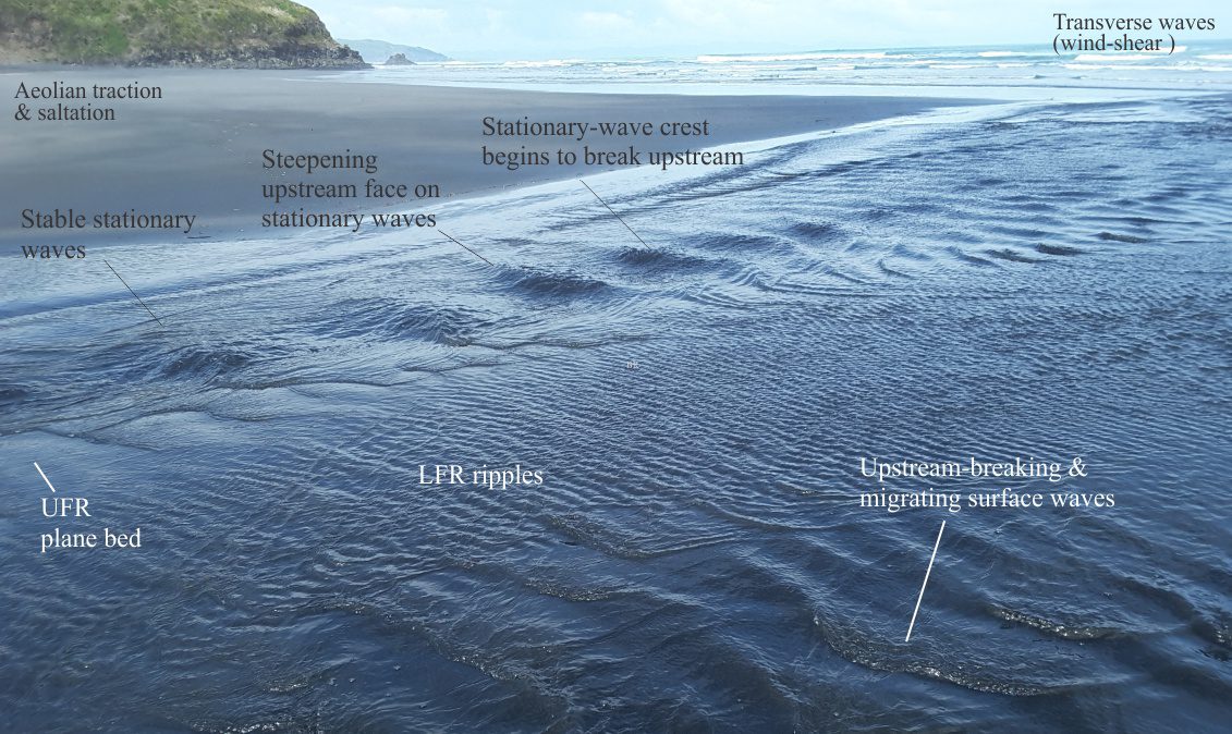
Lithofacies beyond supercritical antidunes

The meeting of waves – a train of supercritical stationary waves flowing towards the coast, subdued by incessant transverse gravity waves parallel to the coast. Manawapu, New Zealand.

Antidune lithofacies

Shallow flow across a beach at low tide – a natural flume. Flow is differentiated into upper (UFR) and lower flow regimes (LFR). The primary focus in the image is the different stages of development and stability for the stationary waves. Other components of the broader depositional setting are also noted. Raglan, New Zealand.

Hummocky and swaley cross-stratification


Cross-section of two HCS-bearing sandstone beds (arrows). Laminae in the lower bed show subtle down-dip thickening (towards the adjacent trough). The amplitude of both mounds is 5-8 cm. The lower bed is overlain by mudstone and sandstone containing asymmetric current ripples (R). Campanian Monster Fm., Yukon.

Low-angle crossbedded sandstone

A section of beach deposits exposed during storm surge erosion and subsequent redistribution of sand to the shoreface. The section contains low-angle crossbeds in well sorted fine- to medium-grained sand – discordant contacts indicated by arrows. The section is parallel to the shoreline (i.e., parallel to depositional strike). Raglan, west coast New Zealand.

Laminated sandstone lithofacies

Parting lineation in Paleogene distributary channel deposits, Canadian Arctic. Resolution of actual paleoflow direction can only be determined from associated crossbed lithofacies.

Tabular and trough crossbed lithofacies

The kind of comparison that never ceases to amaze. Left: Very large, tabular-like crossbedding in the Jurassic Navajo Sandstone, spectacularly exposed at Zion National Park. The dune bedform containing these foresets, at least 18 m high, marched in unison with other dunes across the Middle Jurassic sand-sea. Right: Detail of dune crossbedding in the 3.7 – 2.9 billion year old Stimson formation, probably of aeolian origin, exposed in Gale Crater, Mars (see the recent paper by Banham et al. 2021, Open Access). Contact between crossbed sets is outlined by the dashed line. Note the strongly tangential foresets on lower left. Bar scale is 1 metre. Image credit: enlarged from NASA/JPL-Caltech/MSSS image PIA19818

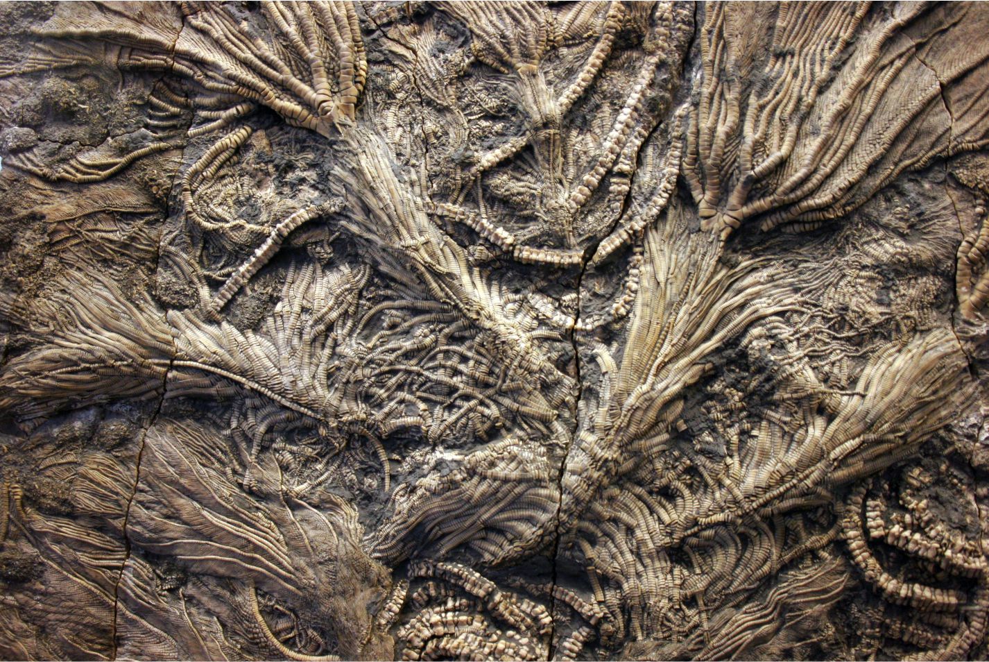
Echinoderm morphology for sedimentologists

A spectacular array of Jurassic stalked crinoids showing many of the defining characteristics of the class – stalk columnals, cirri along the stalks, small calyxes and the spread of arms and pinnules, all in this beautiful cluster. Image credit: Kevin Walsh, Wiki Commons

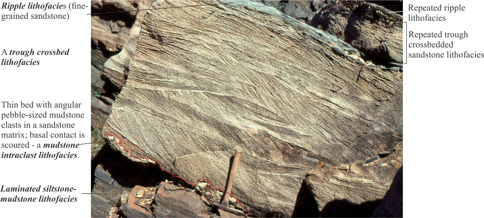
Sedimentary lithofacies – An introduction

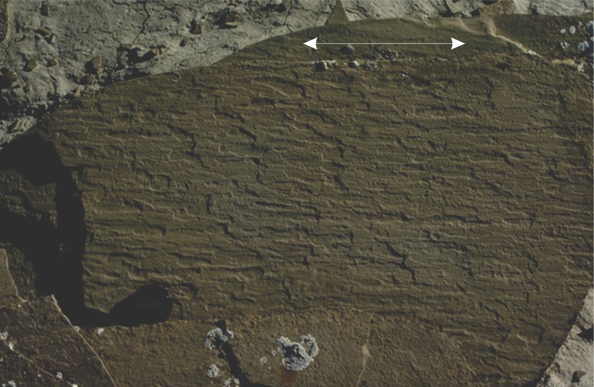
Ripple lithofacies: Ubiquitous bedforms

Climbing ripple lithofacies

Ripple lithofacies influenced by tides


Four lithofacies suffice to describe the complexities of this outcrop from the Paleoproterozoic Rowatt Formation, Belcher Islands. Note that there is no explicit reference to a paleoenvironmental interpretation of the lithofacies.

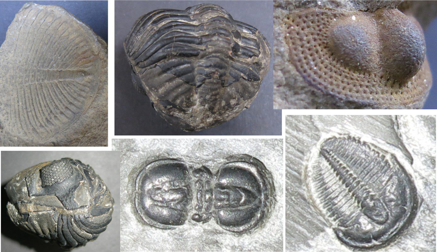
Trilobite morphology for sedimentologists

A montage of some trilobite specimens used in this article

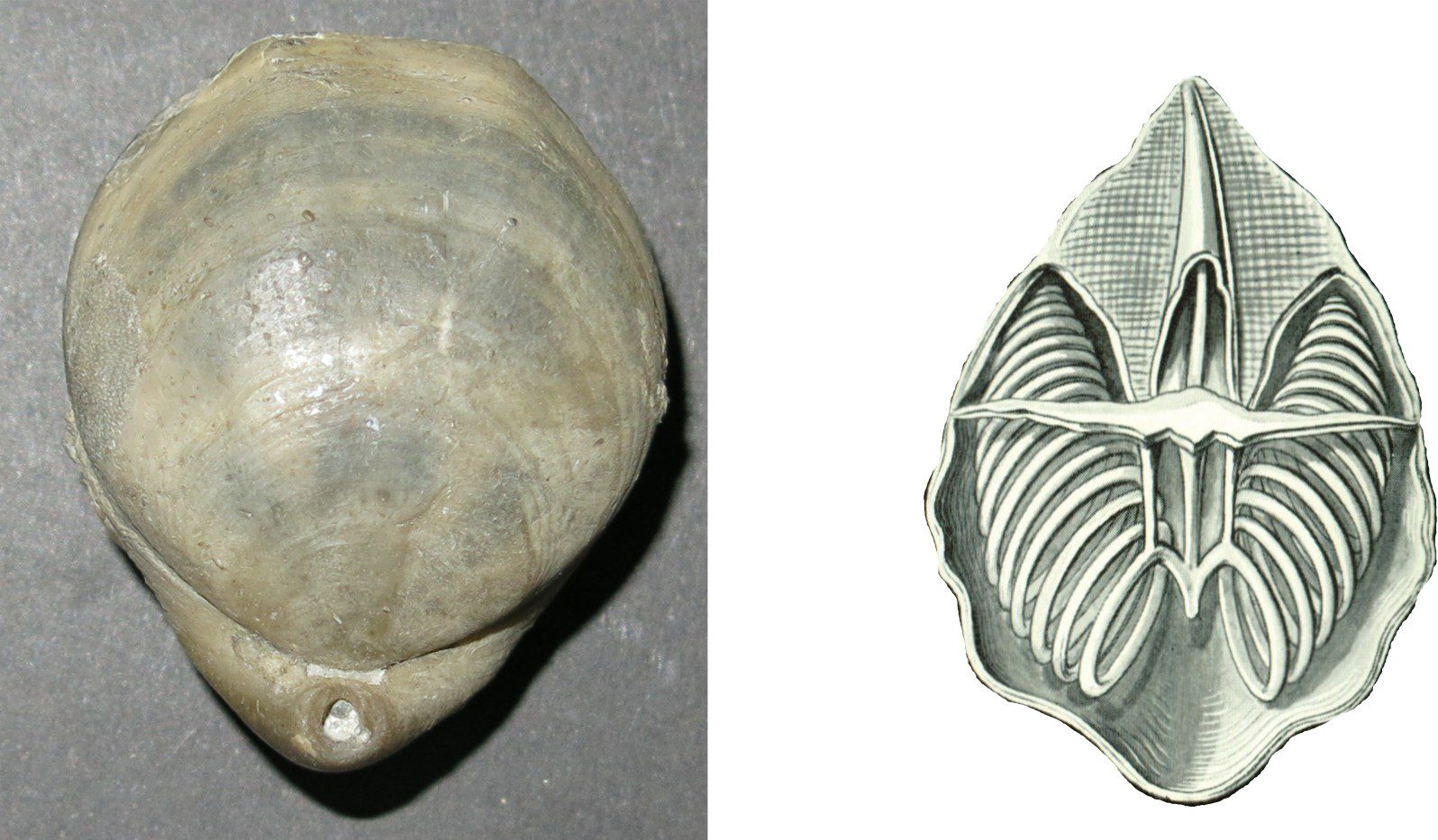
Brachiopod morphology for sedimentologists

A dorsal view (left) of the brachiopod Cererithyris intermedia (Bathonian) showing morphological components such as hinge, pedicle foramen, plications, and growth lines, and (right) an Ernst Haeckel diagram showing the cut-away section of a modern taxon with slinky-like brachidium coils that support the respiratory organ in living forms.

Cephalopod morphology for sedimentologists

Left: The ‘Ram’s horn shell’, Spirula spirula, a loosely coiled (coils barely touching), chambered, internal shell of a small species of squid. The middle fragment shows the calcareous septal neck (a small aragonite tube) extending from the convex side of the septum, that supported the soft siphuncle. The right fragment shows the corresponding port through which the siphuncle extended. The end chamber is anterior; the outer convex shell margin below is ventral; the inner concave margin is dorsal. Spirula shells are composed of aragonite. Right: A collection of Spirula spirula entangled in other flotsam and jetsam (seaweed, wood, plastic) that accumulated along a high tide berm.

Gastropod shell morphology for sedimentologists

The sartorial spendour of spiny Murex – the real show-offs in the world of gastropods. From the left: Chicoreus ramosus (the Ramose Murex, Philippines); Murex pecten (Venus comb Murex, Philippines); Porieria zelandica (New Zealand) – the one I stood on!.

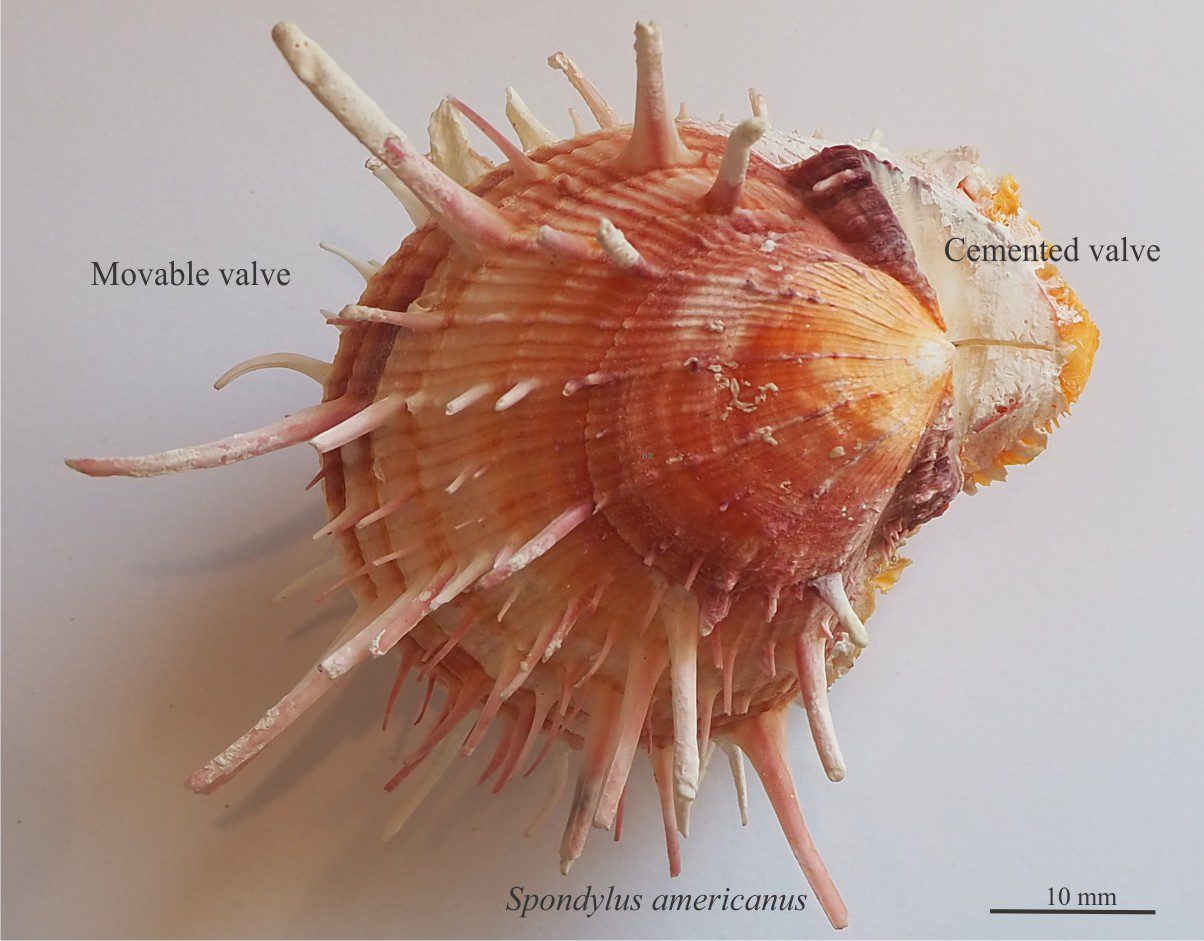
Bivalve morphology for sedimentologists

A very spiny Spondylus americanus – a pectinid and member of the oyster family. The lower valve was attached.

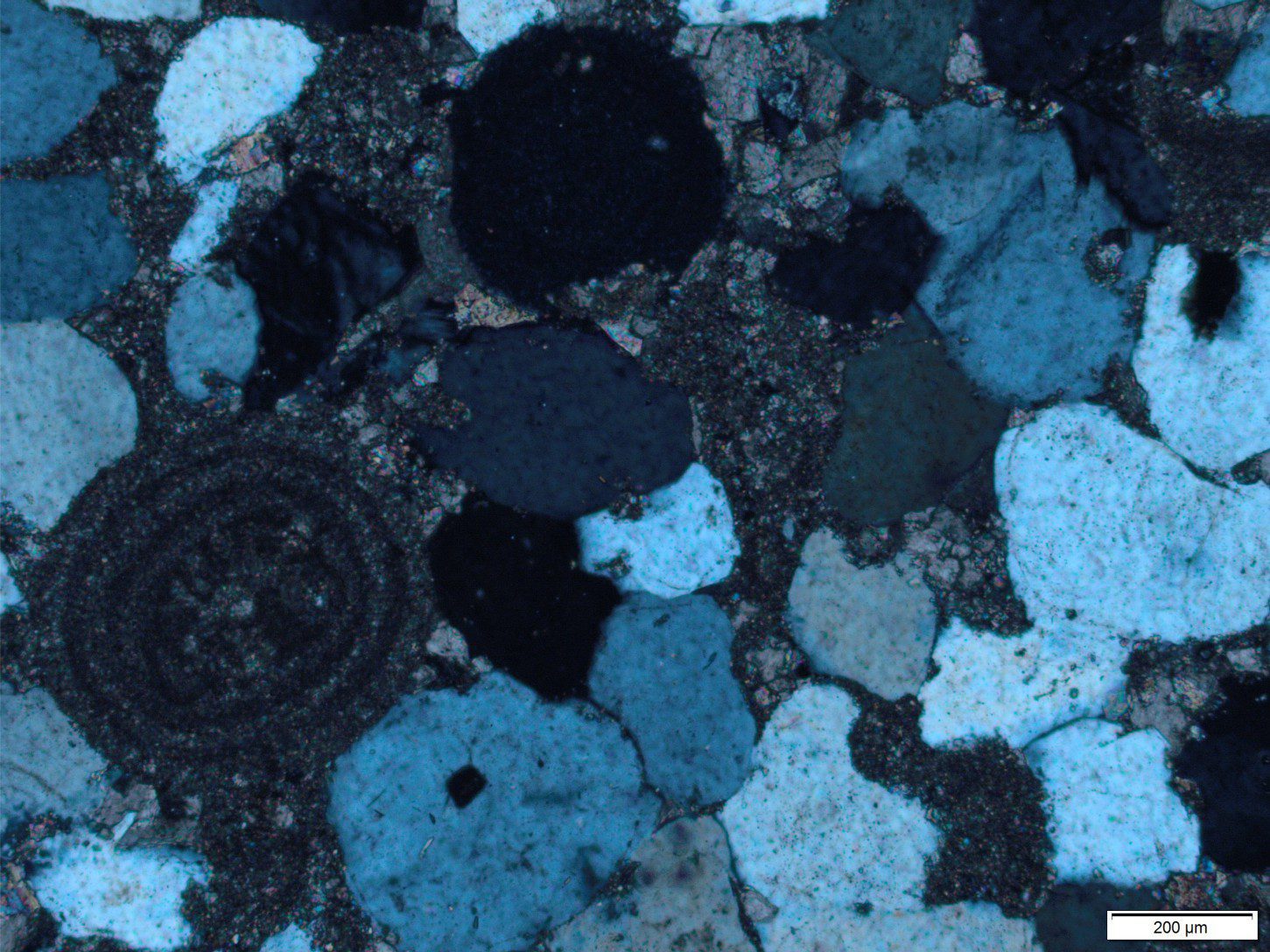
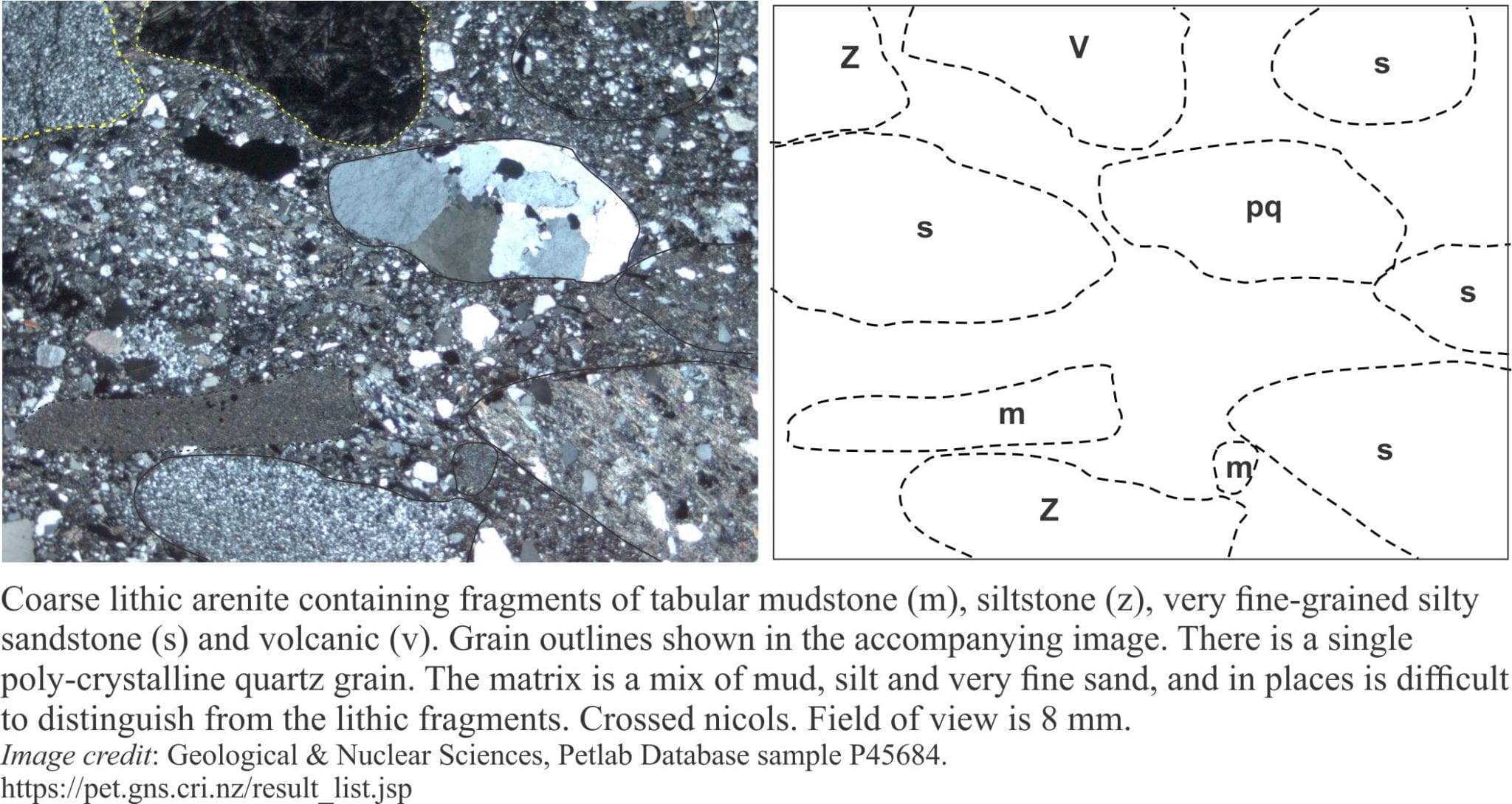
Lithic grains in thin section – avoiding ambiguity

Green schist hypothetically ‘eroded’ and whittled progressively to finer grain sizes

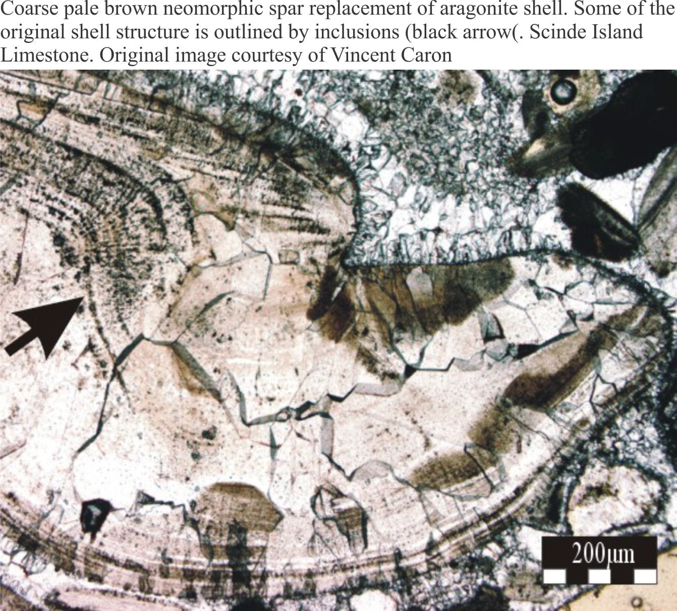
Neomorphic textures in thin section

Intragranular calcite cement in bryozoa pores https://www.geological-digressions.com/carbonates-in-thin-section-bryozoans/ (the much smaller, dark, circular bodies within the bryozoan structure are zooids). Cementation began with small, bladed calcite crystals lining pore walls, overlain by coarser, more-or-less equant spar. Most intercrystal boundaries are straight. Boundaries that appear curved actually consist of smaller, straight-edge segments. Left: Plain polarized light. Right: Crossed polars. Sample is from the Oligocene Te Kuiti Group.

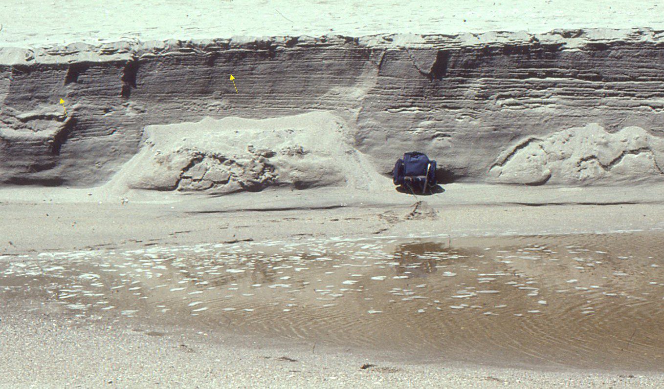
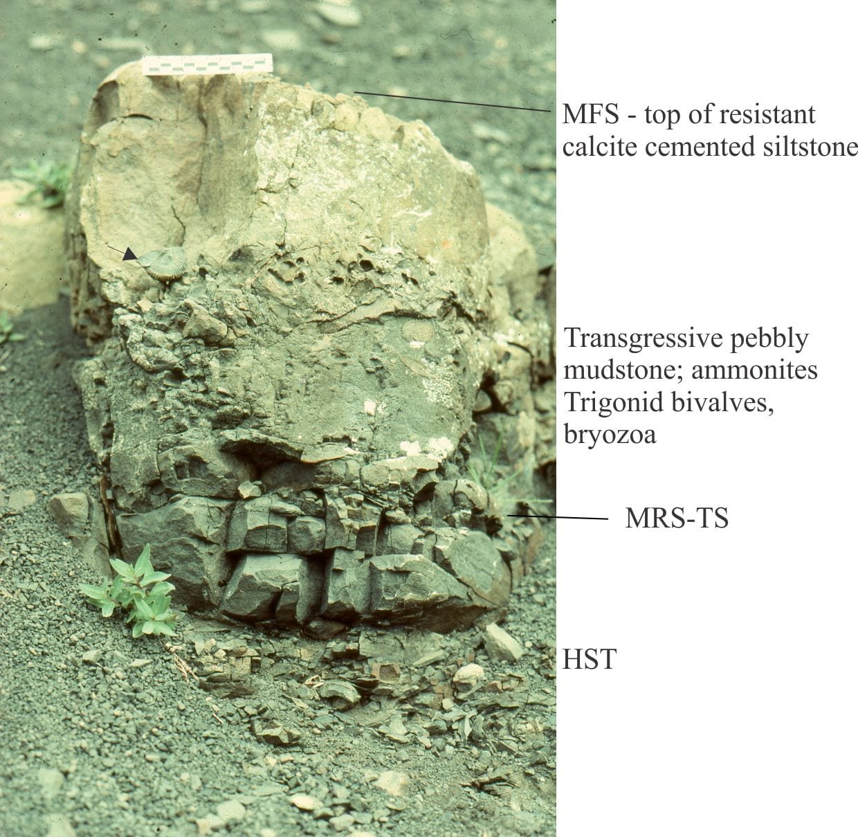
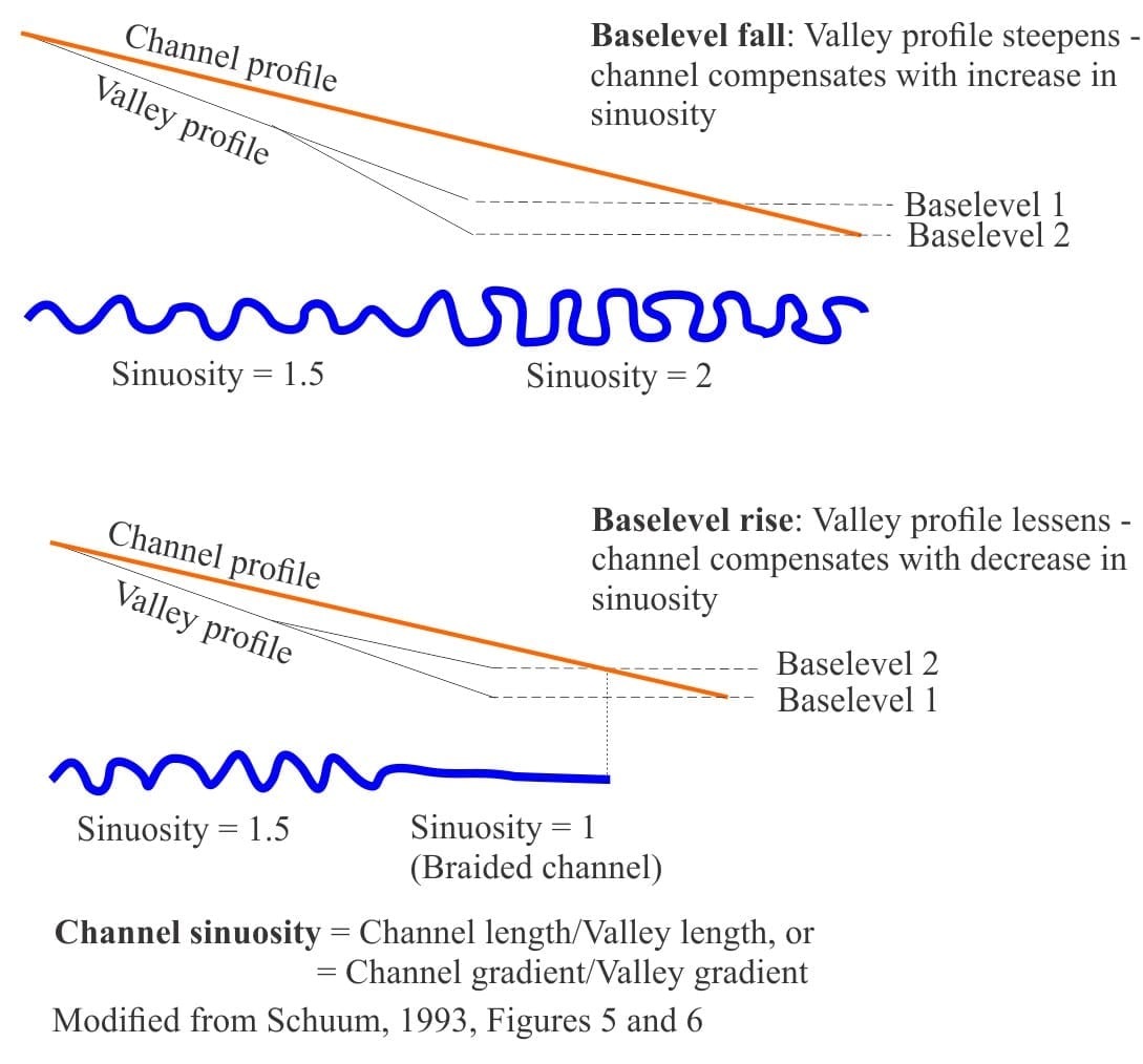
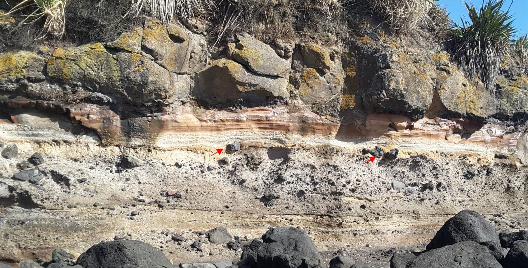
Stratigraphic surfaces in outcrop – baselevel fall

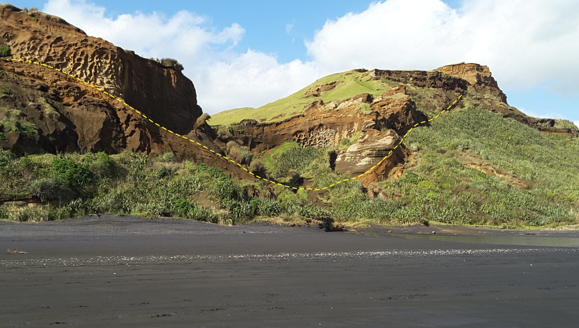
Stratigraphic surfaces in outcrop – baselevel rise

A modern diastemic ravinement (SR-D) developing in an estuary along the south Auckland coast, New Zealand. Salt marsh deposits are gradually being eroded by encroaching intertidal and subtidal sands. The left image shows remnants of the salt marsh muds and dead or dying mangroves with roots exposed by erosion. The right image shows some detail of the eroded marsh deposits, where the roots of Salicornia and rushes are exposed. Most of the open holes were formerly occupied by roots that decayed once they were exposed. Excavations through these deposits show that about 90% of the salt marsh unit will be removed, leaving only a veneer preserved in the rock record.

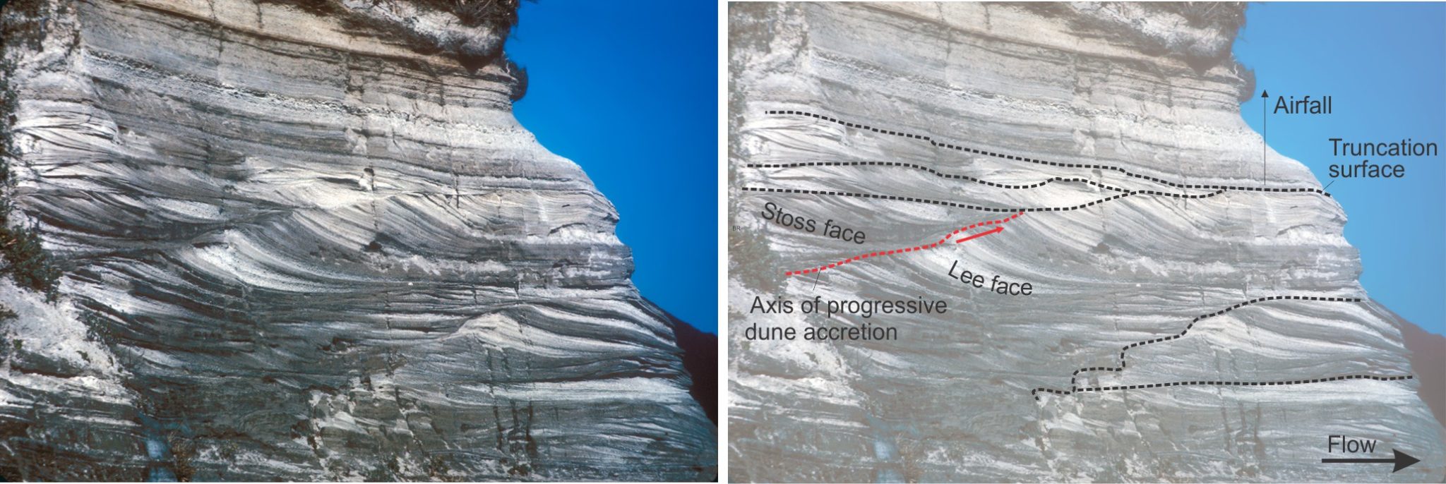
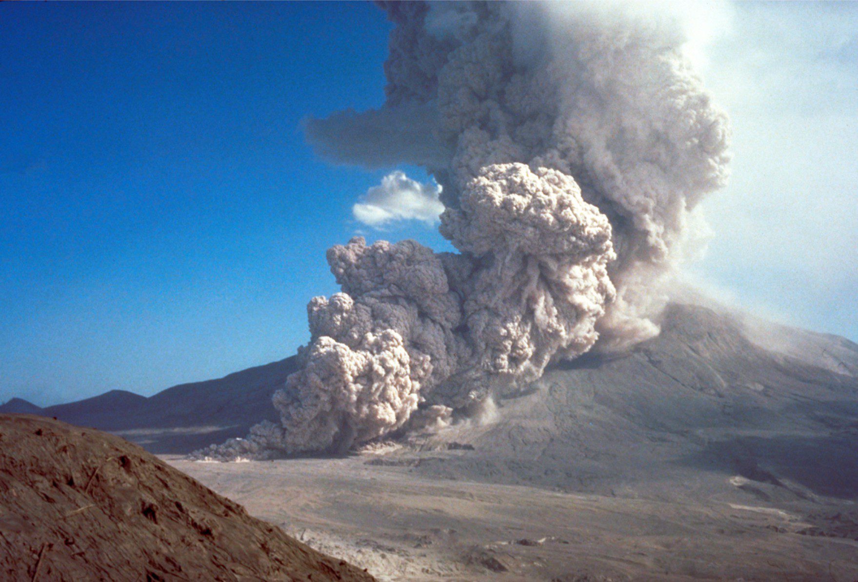
Pyroclastic surges and base surges

Numerous truncation surfaces (black dotted lines) in this deposit indicate multiple, closely timed and spaced pyroclastic surges. The surge unit at centre-left preserves both stoss and lee slope laminae of a dune that aggraded and prograded down flow (to the right) – the axis of progressive accretion shown by the red dotted line represents the dune crest. The surge deposits are overlain by airfall tephras. The surges originated from lava dome collapse on Mukaijima, part of the Izu-Bonin-Mariana volcanic arc south of Honshu, Japan, that last erupted about 1300 years ago. Image credit: R.V. Fisher, 1979 (University of California Santa Barbara) and Smithsonian Institution.

Accretionary aggregates and accretionary lapilli

Late Pleistocene airfall ash and lapilli deposits deposited during an explosive (phreatomagmatic) maar eruption (Ihumatao, west Auckland, New Zealand). The darker layers contain greater proportions of basaltic lapilli. The lighter-coloured ash layers (at the lens cap) contain abundant accretionary lapilli.

Block and ash flows


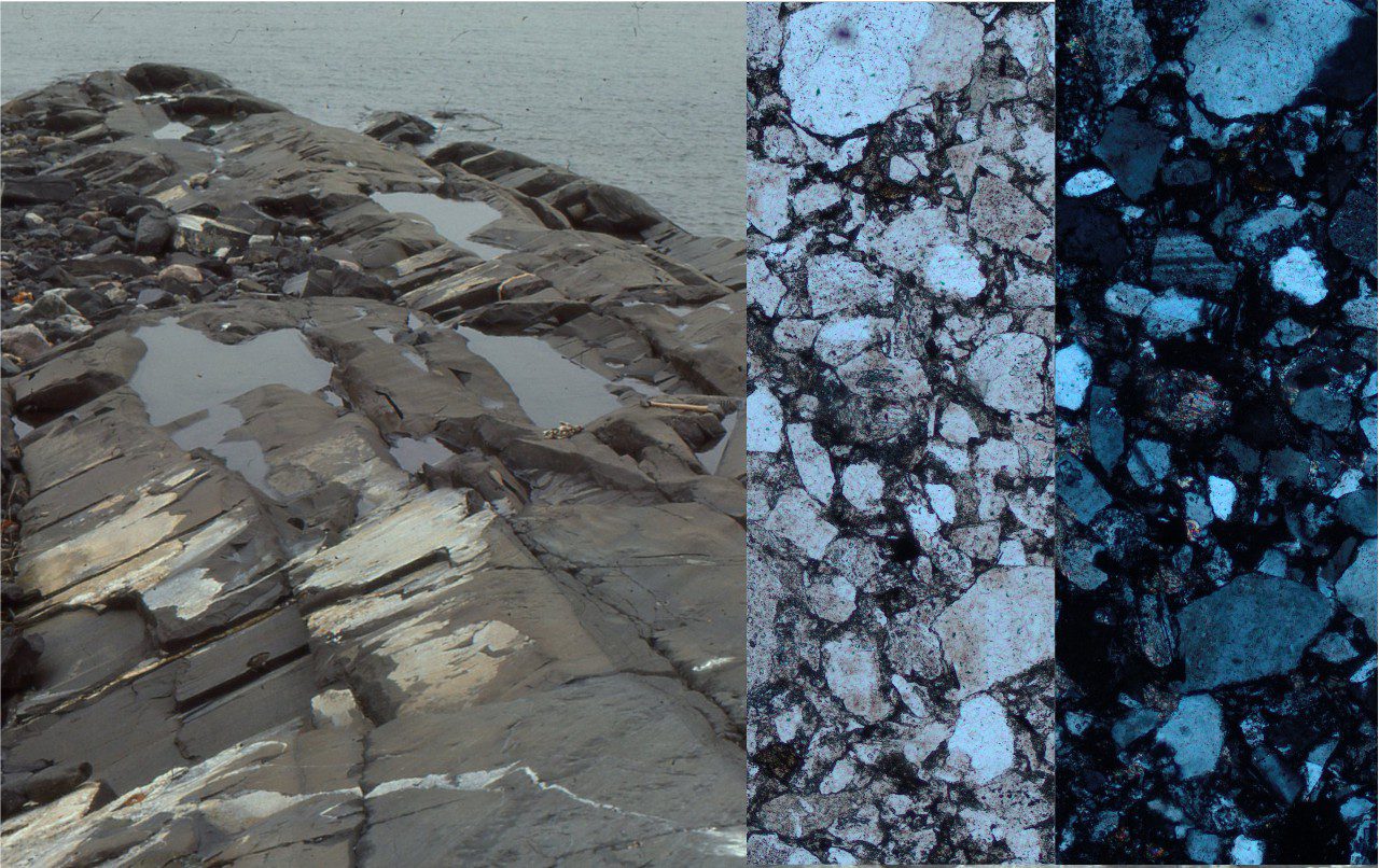
Ignimbrites in outcrop and thin section

Multiple flow units in a Mid Miocene welded ignimbrite, Chilean Altiplano.

Glauconite in thin section

Glauconite filling of rotaliid foram chambers


Carbonates in thin section: Forams and sponges

A couple of rotaliids in various states of comminution (possibly Amphistegina – the one labelled ‘r’ is broken along its left margin), and an evolute planispiral foram (centre) in bioclastic grainstone that also contains plenty of bryozoa (b), echinoid plates (e) and spines, and barnacles (ba). The central foram is partly filled with glauconite. Oligocene, New Zealand. Plain polarized light.

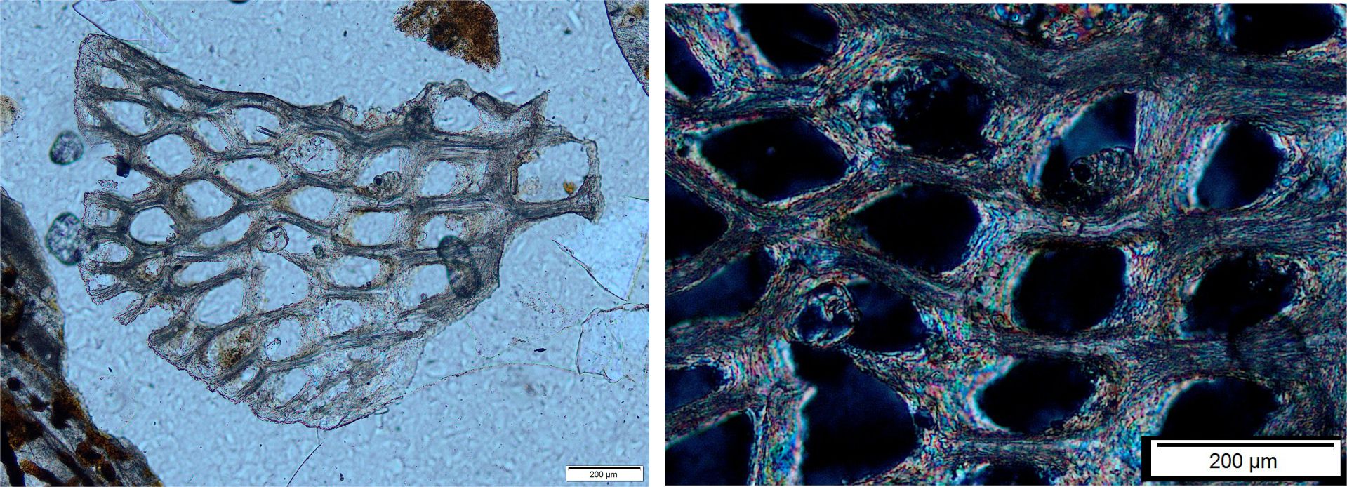
Carbonates in thin section: Bryozoa

An abraded fragment of modern, lacey or platy bryozoa showing variable zoecium size (average 200 μm zoecium width) and shape. Zoecia walls are constructed with fibrous aragonite crystals that, in the expanded view (right - crossed polars), are crudely aligned parallel to zoecia walls. Offshore Three Kings Islands, northern (subtropical) New Zealand, about 30 m depth.

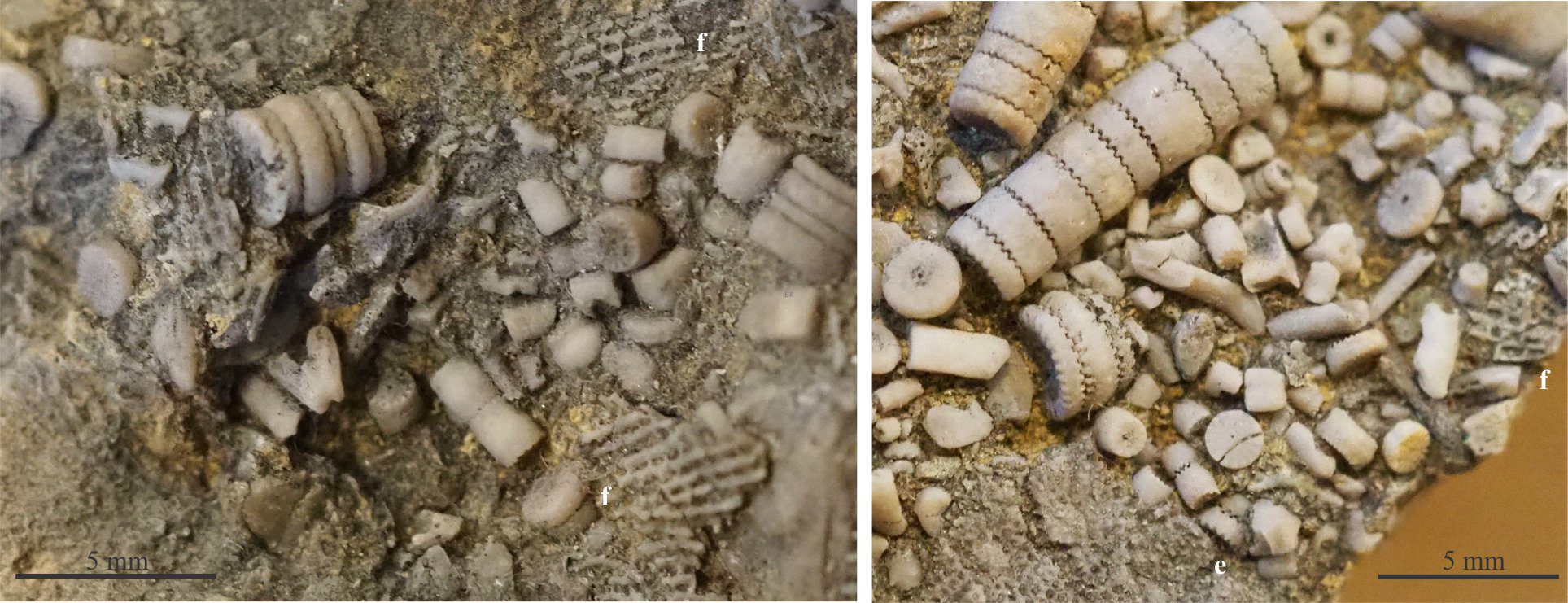
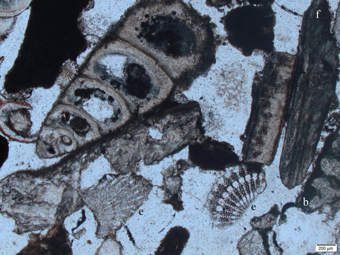
Carbonates in thin section: Echinoderms and barnacles

Devonian crinoid stems and disarticulated columnals in the bioclastic mix with fragmented fenestrate (f) and encrusting bryozoans (e).

Carbonates in thin section: Molluscan bioclasts

A small, turreted gastropod. The main layer is prismatic aragonite. There is a thin foliated layer between each whorl. The whorl cavities are also lined with fibrous aragonite cement. In the bioclastic mix are echinoderm spines (e), barnacle fragments (b), and a couple of bivalve or gastropod fragments (f) with well-defined foliated structures. Plain polarized light. Recent beachrock, Hawaii.


Volcanics in outcrop: Pyroclastic density currents

A ground-hugging pyroclastic density current and associated buoyant plume generated by column collapse at Mt St. Helens August 7, 1980, almost 3 months after the devastating eruption and lateral blast (May 18). Image credit: Peter Lipman, USGS.

Fluid flow: Froude and Reynolds numbers

Schematic representation of laminar and turbulent flow using hypothetical flow lines. The blue arrow (right) indicates mean flow velocity for turbulent flow.

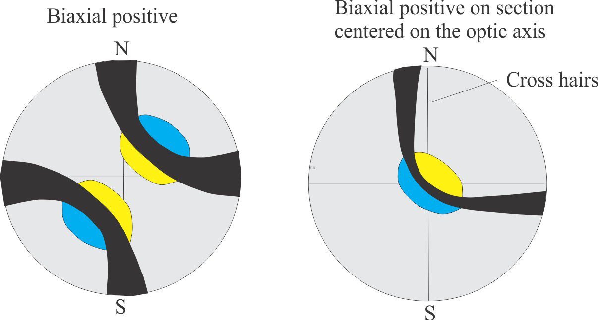
Optical mineralogy: Some terminology

Determining the sign for biaxial minerals from interference figures, using an accessory plate

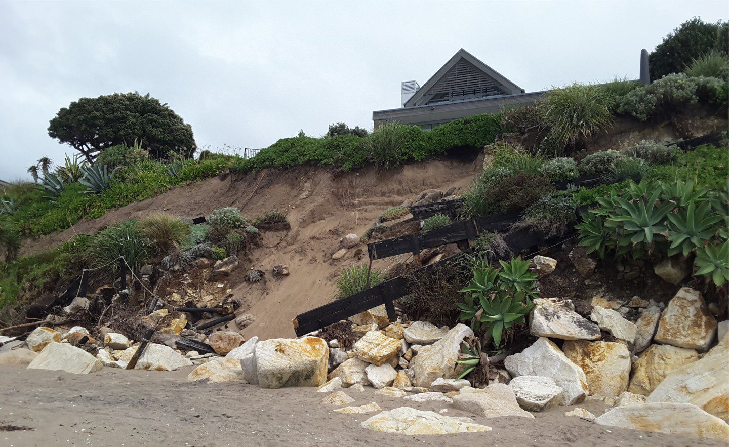
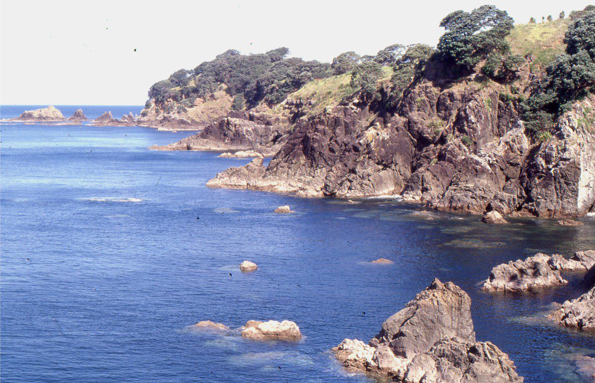
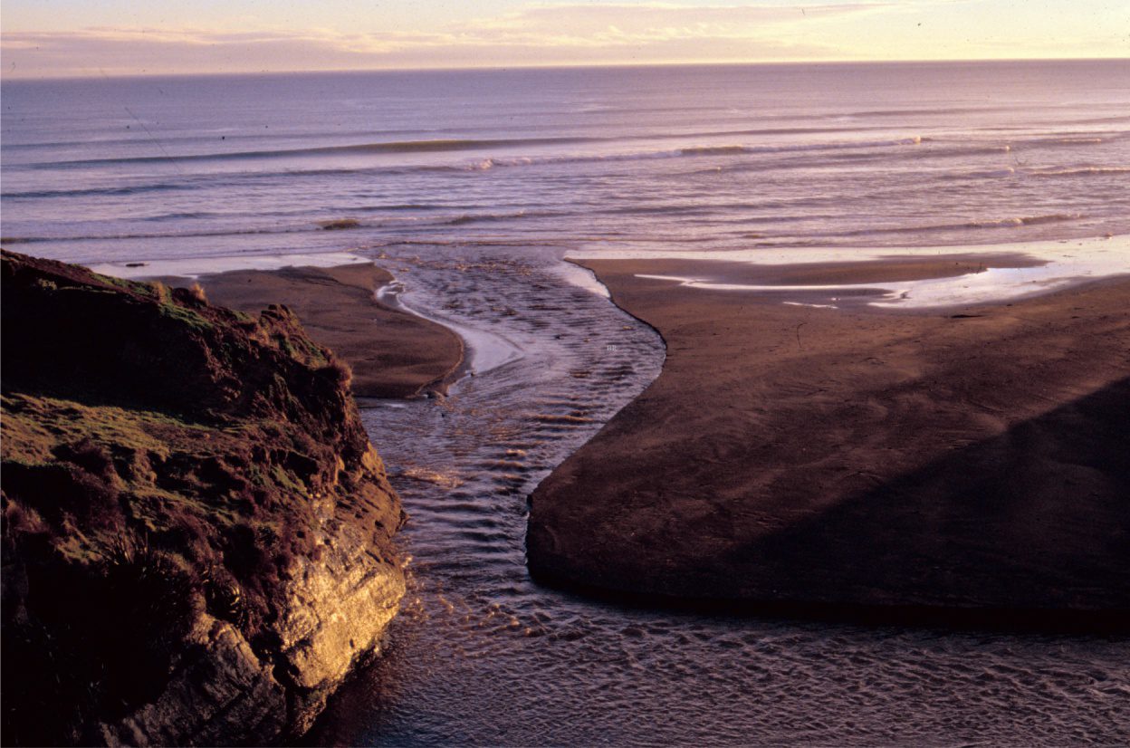
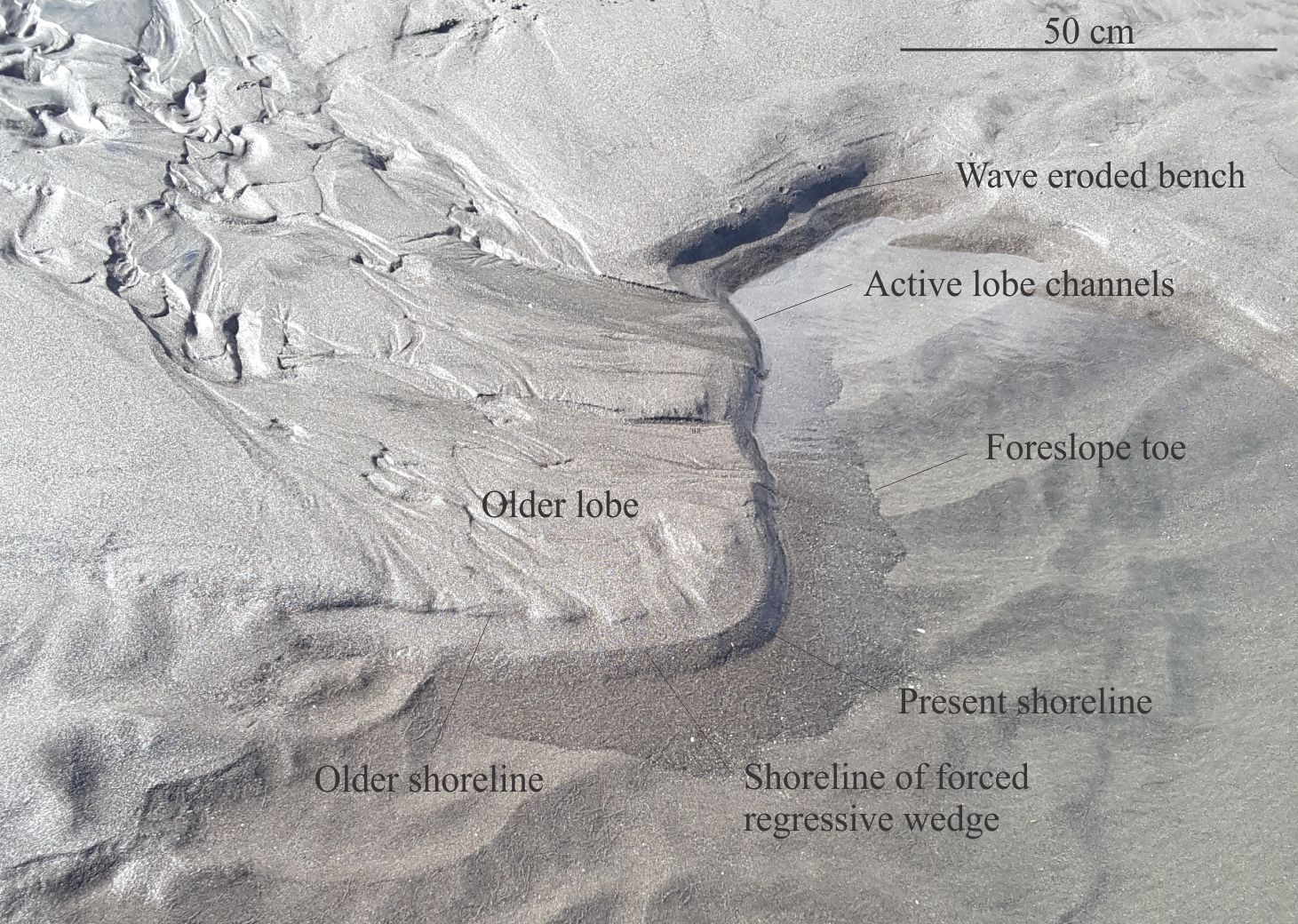
Beach microcosms as fan delta analogues

Two, merged fan delta lobes, the active one at top centre. In this scenario, delta progradation has kept pace with sediment supply (or close to it) during baselevel fall, resulting in a narrow zone where delta growth extends beyond an earlier shoreline. The new shoreline is located at the active shoreline-foreslope break. This pattern of downstepping progradational shoreline packages is analogous to a forced regressive systems tract. The presently active channel continues to supply sand, forcing the shoreline downward and basinward onto a second forced regressive package.

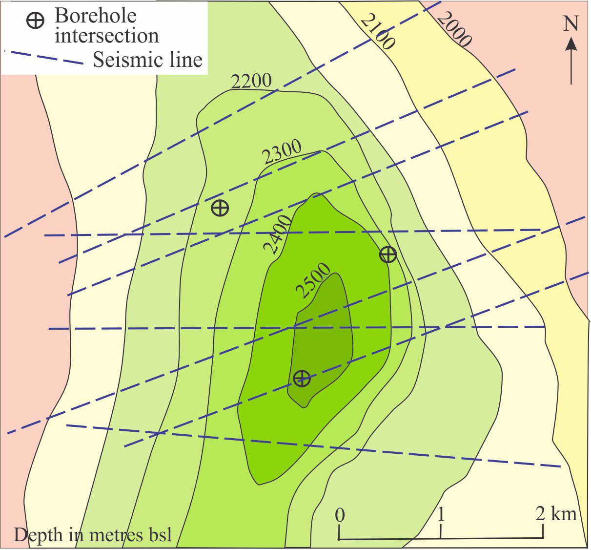
Plotting a structural contour map

Mapping the structural contours across a stratigraphic unit reveals a three-dimensional picture of its subsurface distribution, deformation, structural relief, and stratigraphic displacement along faults. The structure here is a north-plunging, asymmetric anticline, its eastern limb the steepest. The data needed for this exercise is usually acquired from borehole intersections and velocity-depth conversions from seismic profiles.

A submarine channel complex

Excellent exposure of a submarine channel stack on Todagin Mountain, northern British Columbia. Tracings of the channel outlines are shown on the right. Working on the slopes above the cliff required care because of a treacherous veneer of ball-bearing like shale shrapnel on the steep surface. Points A to D locate the examples shown below.

Greywackes in thin section

Typical greywacke in outcrop and thin section

Sandstones in thin section

Calcite cemented subarkose, Proterozoic Altyn Fm. southern Alberta

Geohistory 2: Backstripping tectonic subsidence

Geohistory 1: Accounting for basin subsidence

A schematic trajectory of stratigraphic units following sequential decompaction – the result helps to describe the subsidence and uplift history of a sedimentary basin.

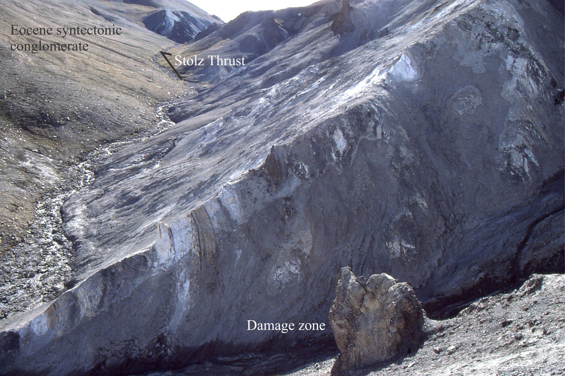
Geofluids: The permeability of faults

Damage zone in the hanging wall of Stolz Thrust (Eocene); Footwall contains Middle Eocene syntectonic conglomerate, Axel Heiberg Island, Canadian Arctic. The zone consists of open drag folds in interbedded sandstone (white) and shale, and significant shearing that has obliterated some of the original bedding. The bulk permeability in this zone is low. The zone in this view is about 20 m wide.


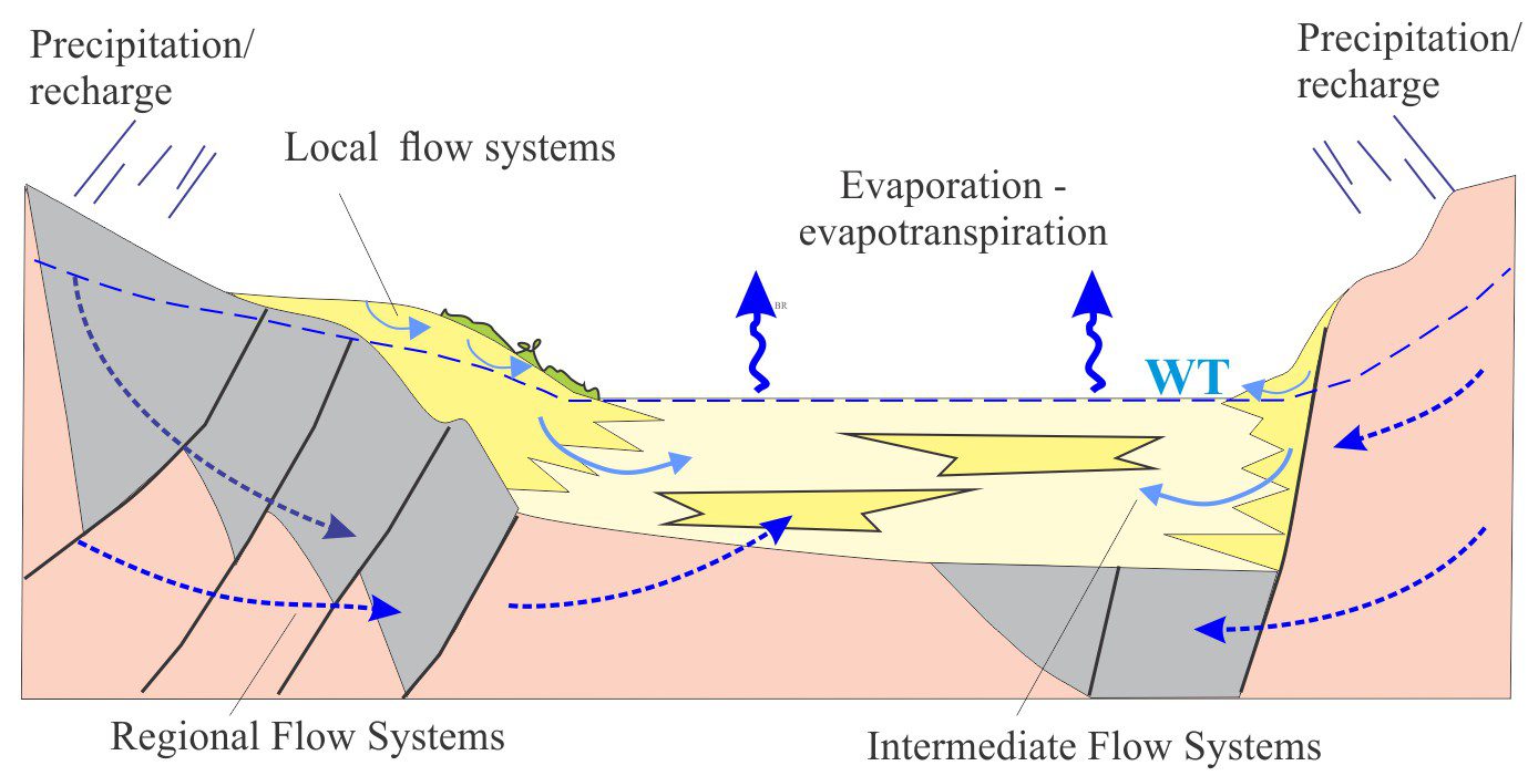
Geofluids: Sedimentary basin-scale fluid flow

Groundwater flow systems in a small drainage basin. The flow systems are nested according to Toth’s (1963) vision of groundwater partitioning at local, intermediate, and regional scales. Vertical scale in 100s of metres; horizontal scale in 10s to 100s of kilometres.


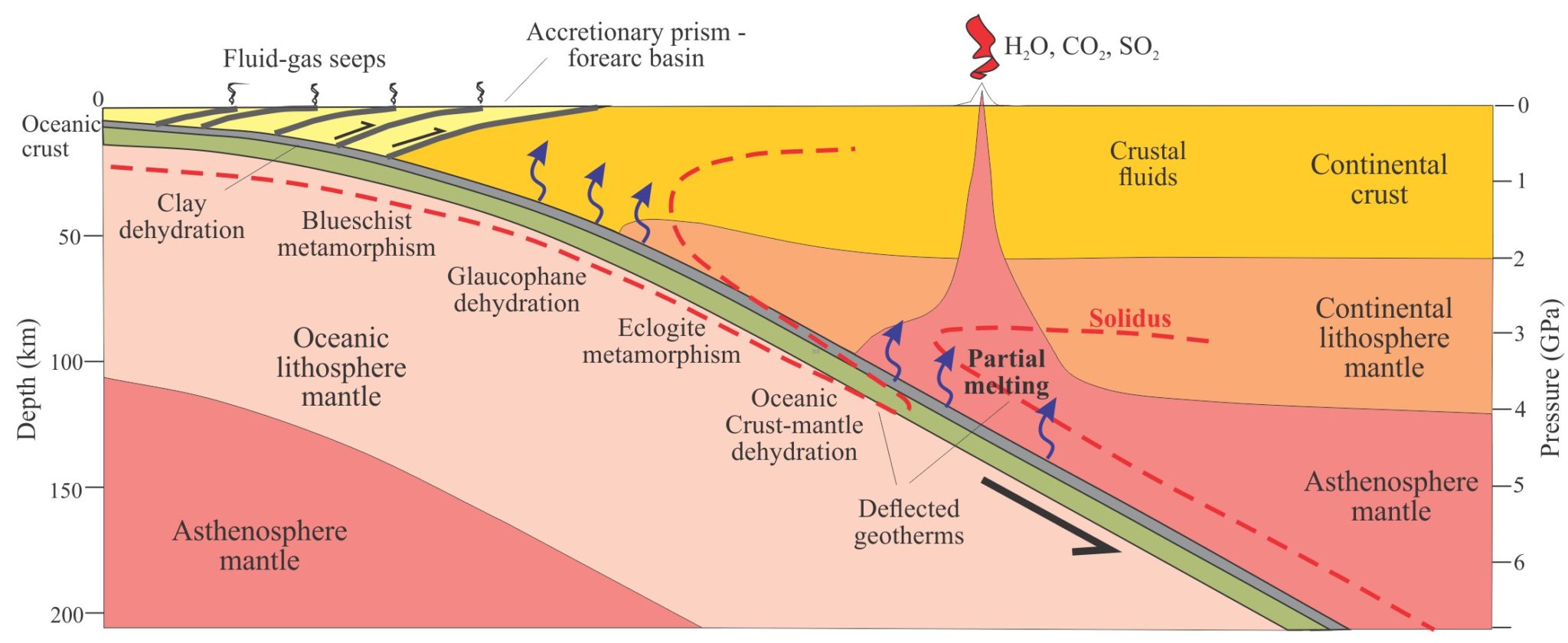
Geofluids: Lithosphere-scale fluid flow

The origin and fate of fluids generated by subduction of oceanic lithosphere, the partial melting of asthenosphere mantle, and the formation of a magmatic arc. Some fluid in the oceanic crust is recycled to the deep mantle. Fluid flow in the accretionary prism is driven by compaction, tectonic compression, and clay dehydration. Note the deflection of geotherms by descending, cold, oceanic lithosphere. Modified from Farsang et al., 2021 and Miller 2013.


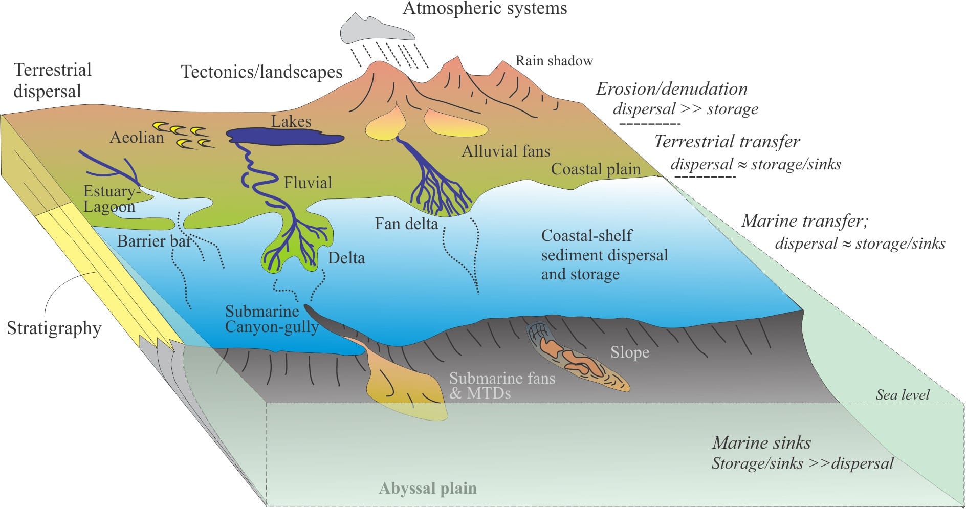
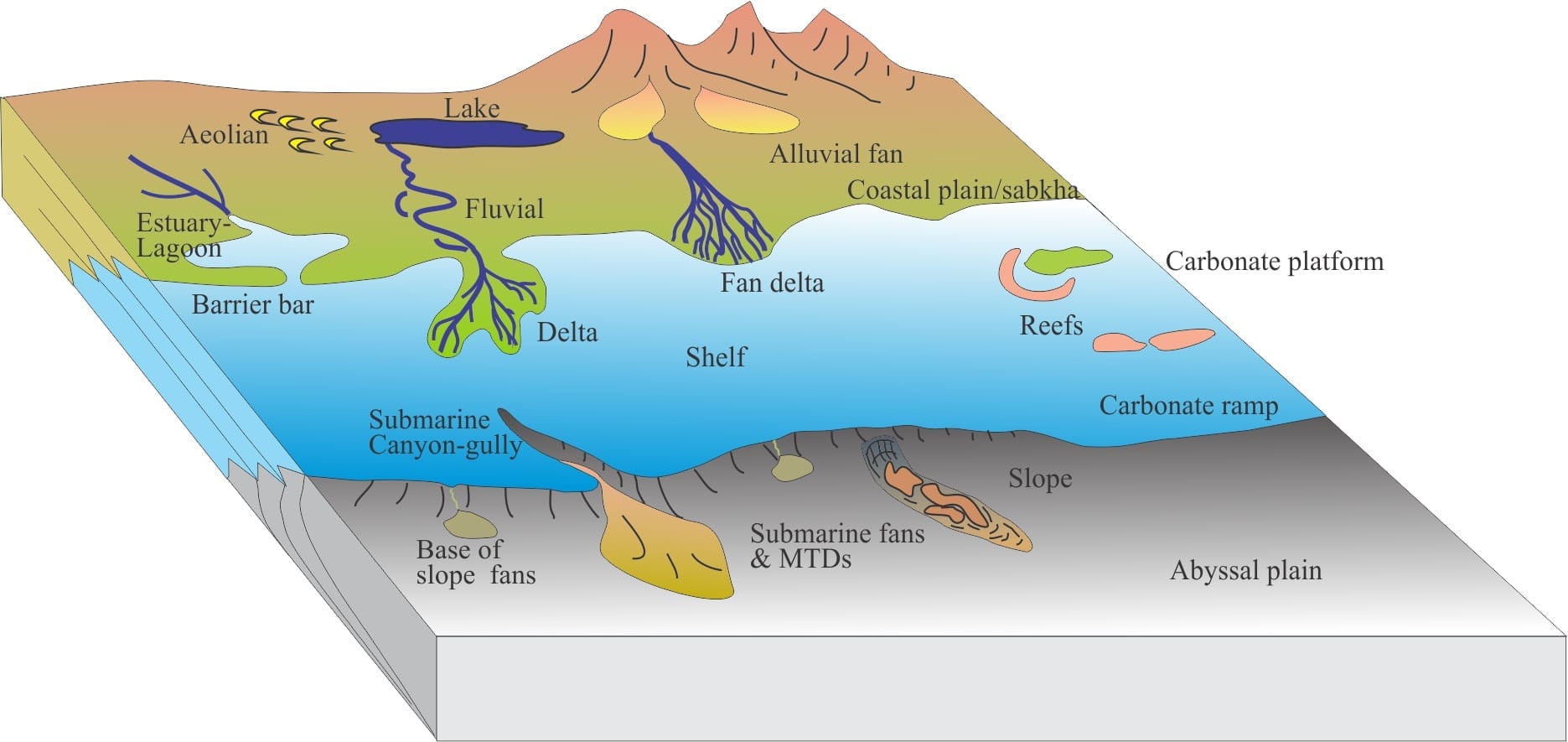
Source to sink: Sediment routing systems

An attempt to show schematically, the linkages among the components of sediment routing systems: the source area (the erosion engine), the transfer zone, and sinks. In each zone, sediment may be stored temporarily, or accumulate in sinks if there is sufficient long-term accommodation.


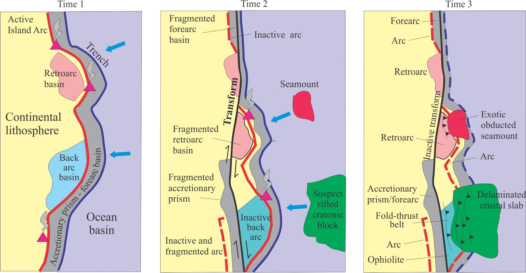
Allochthonous terranes – suspect and exotic

A hypothetical collegiate of terranes across an orogen, transported by strike-slip dislocation, subduction, and obduction. Distances travelled are measured in 100s of kilometres. Modified quite a bit from Helwig, 1974, Fig.1.


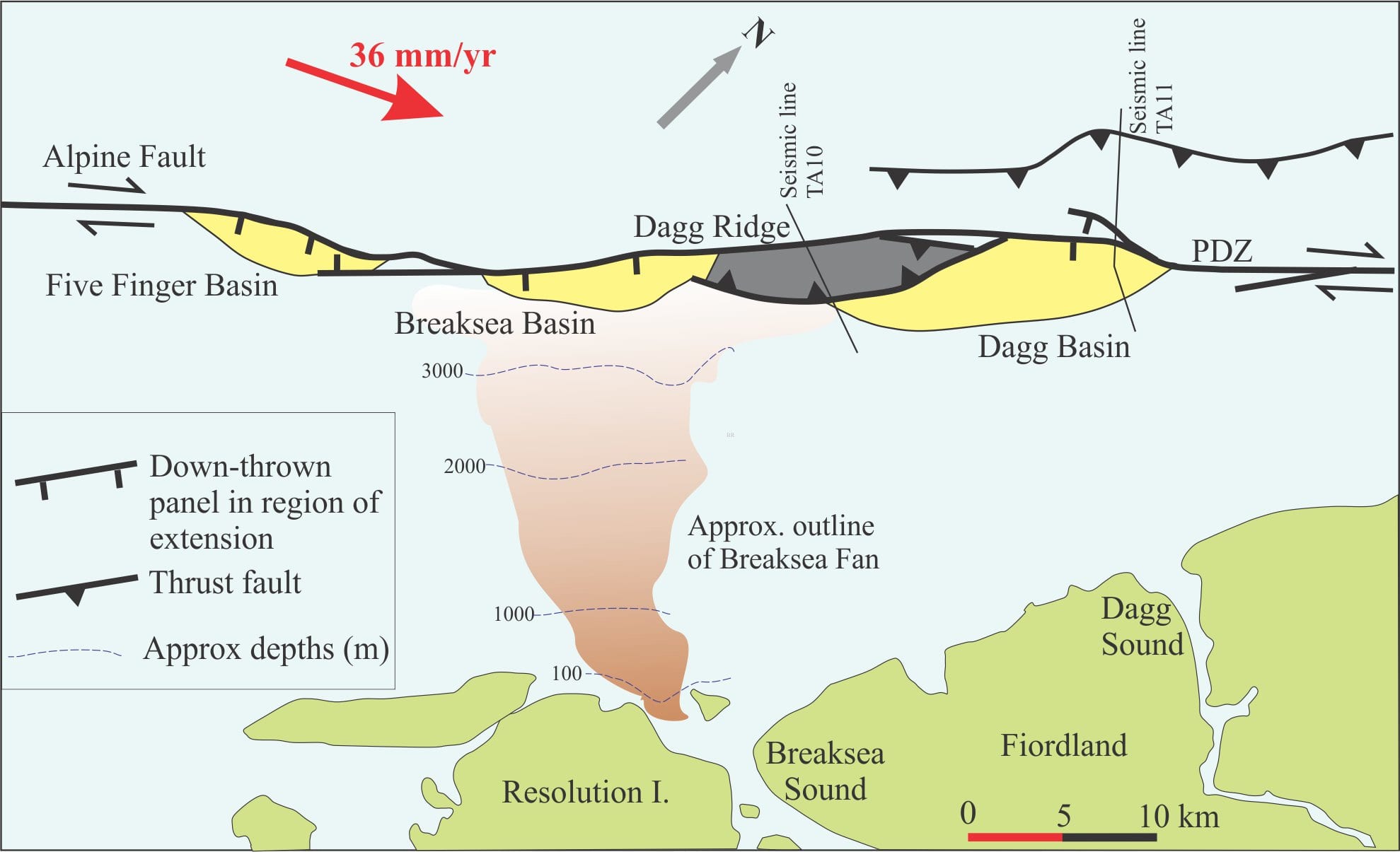
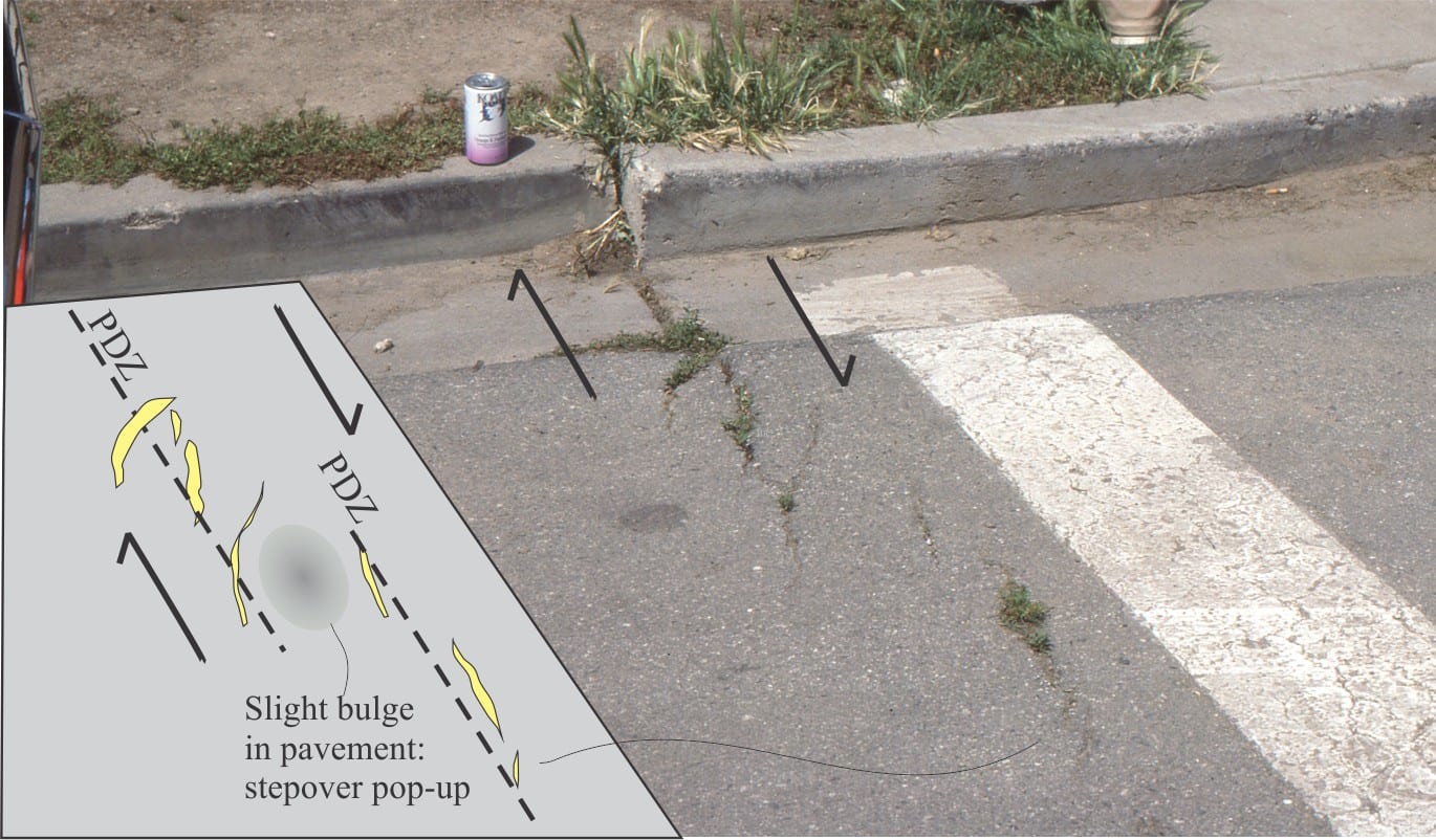
Basins formed by strike-slip tectonics

A segment of offshore Alpine Fault, west Fiordland. The PDZ is a series of linked Fault segments most of which have right-lateral displacement. Narrow Five Finger Basin and Dagg Basin are forming at right-handed releasing bends; Breaksea Basin forms at a right-stepping overstep. The southwest end of Dagg Basin is being inverted at the same time that it is subsiding farther north. Dagg and Breaksea basins are separated by Dagg pop-up ridge (Note the reverse fault that defines the south ridge boundary), but the two basins may be connected. Sediment supply is mainly from Breaksea submarine fan. Modified from Barnes et al. 2005, Fig. 10.


Strike-slip faults: Some terminology

A mini-example of right-lateral strike-slip deformation associated with the 1984 earthquake on Calveras Fault at Hollister; the fault is a major splay of the San Andreas transform. Tension gashes formed in the pavement have a broadly en echelon, sigmoidal orientation, and appear to be offset at a pop-up step over – the inset left is a sketch of the interpreted structures. This photo taken in 1988.

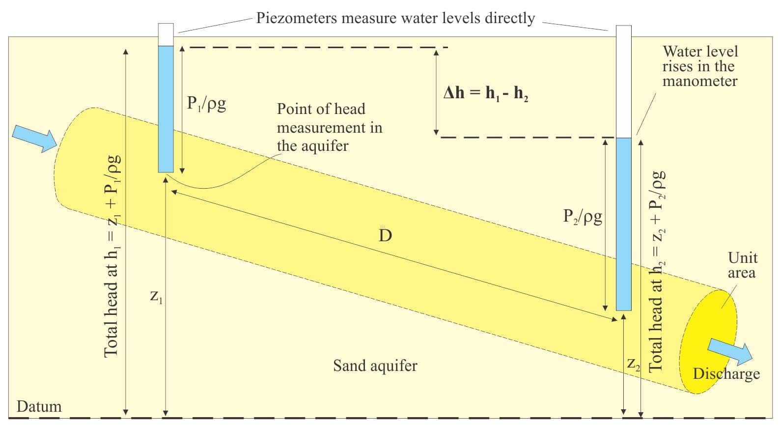
Henry Darcy’s Law; a conceptual leap

An alternative representation of Darcy’s experiment, shown as tube (pipe) flow in a sand aquifer. Instead of mercury manometers, the piezometers measure the water levels directly, relative to a datum. Each water level represents the total hydraulic head at the point of measurement in the aquifer. The distance D between piezometers allows the calculation of hydraulic gradient.


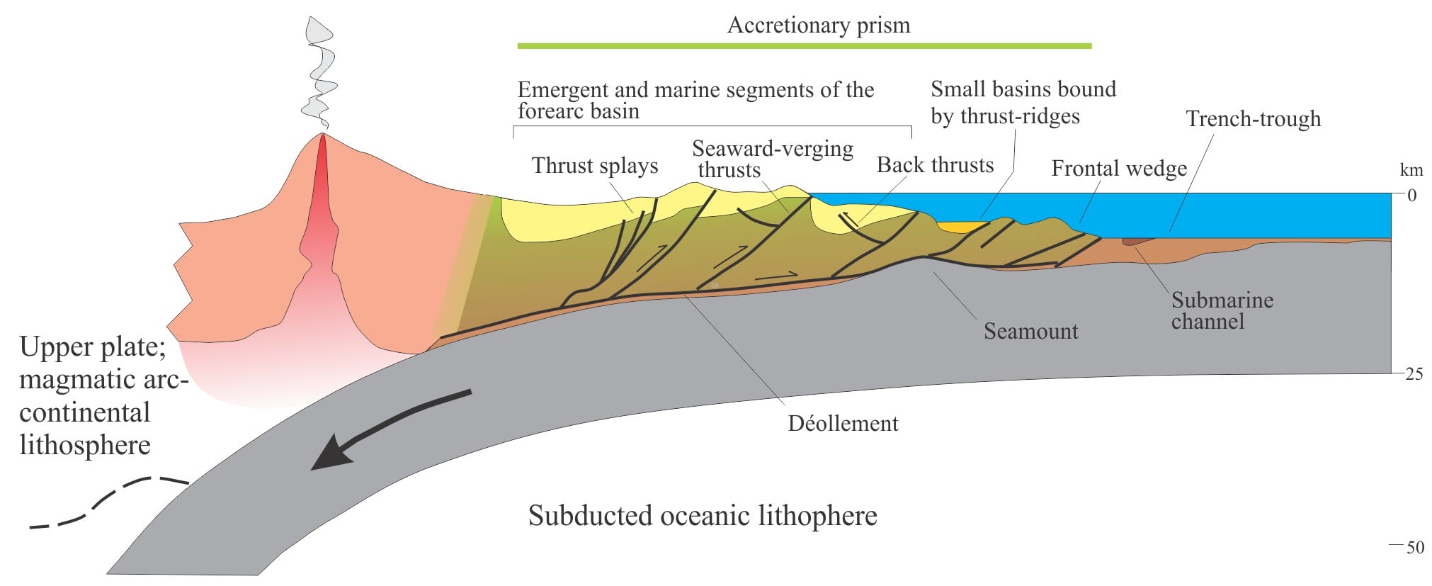
Accretionary prisms and forearc basins

An accretionary prism and forearc basin above a subducting slab of oceanic lithosphere, with a magmatic arc as structural backstop (or buttress) and the main source of sediment.


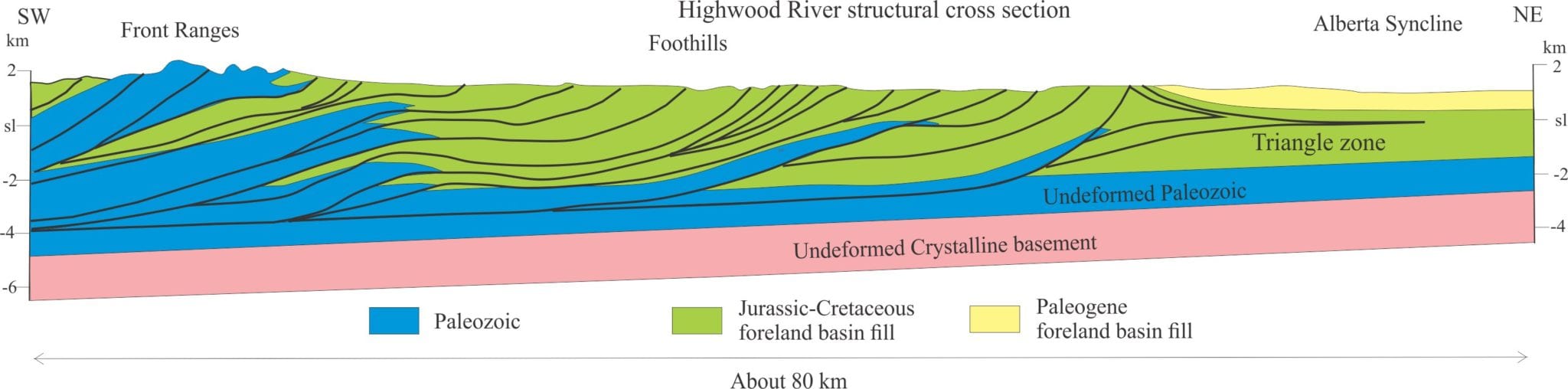
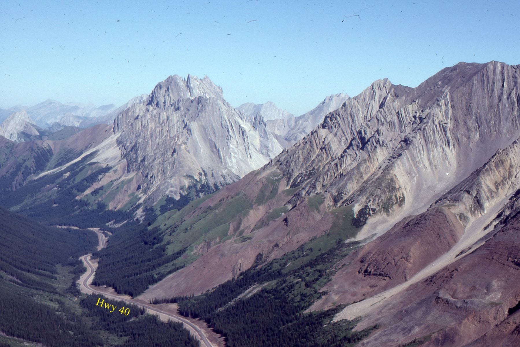
Thrust faults: Some common terminology

Structural cross-section of part of the Alberta foreland fold-thrust belt, south of Calgary. The belt terminates in a triangle zone. The décollement is in carbonate and siliciclastic rocks that formed part of a broad miogeoclinal succession on the Paleozoic margin of North America. Jurassic-Cretaceous strata deposited in the Western Interior Foreland Basin became involved in the deformation. Section has been simplified from Wright et al, Chapter 3, Figure 3.13. https://ags.aer.ca/reports/atlas-western-canada-sedimentary-basin (PDFs available)

Sedimentary basins: Basins formed by lithospheric flexure

Part of the Alberta Front Ranges fold -thrust belt north of Highwood Pass. Sawtooth-like Lower Paleozoic carbonates are exposed as flatirons in the hanging wall of a thrust immediately east of Lewis Thrust. Late Jurassic – Early Cretaceous foredeep deposits in the valley floor (mostly covered) were involved in the deformation as the orogenic load migrated eastward. Orogenic transport to the right.


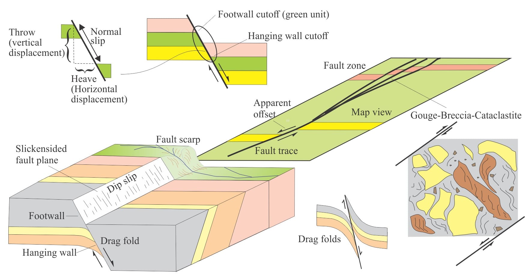
Faults – some common terminology

A schematic summary of fault terminology and indicators of displacement


Stereographic projection of linear measurements

Sedimentary basins: Nascent conjugate, passive margins

Two profiles across the north (Line 6N) and south (Line 5S) margins of Gulf of Aden interpreted from seismic. Both show the transition from continental crust to crust that is transitional to oceanic. Syn-rift deposits occupy half grabens bound by basin-dipping listric faults, and in turn are unconformably overlain by nascent post-rift, passive margin successions. Prograding clinoforms are well developed in the post-rift succession in Line 6N. Part of the post-rift stage at the basinward end of profile 6N is interpreted as coeval with the continental-oceanic crust transition that probably developed at the beginning of sea floor spreading; the stratigraphic package here includes volcanic accumulations. Modified from Nonn et al. 2019.

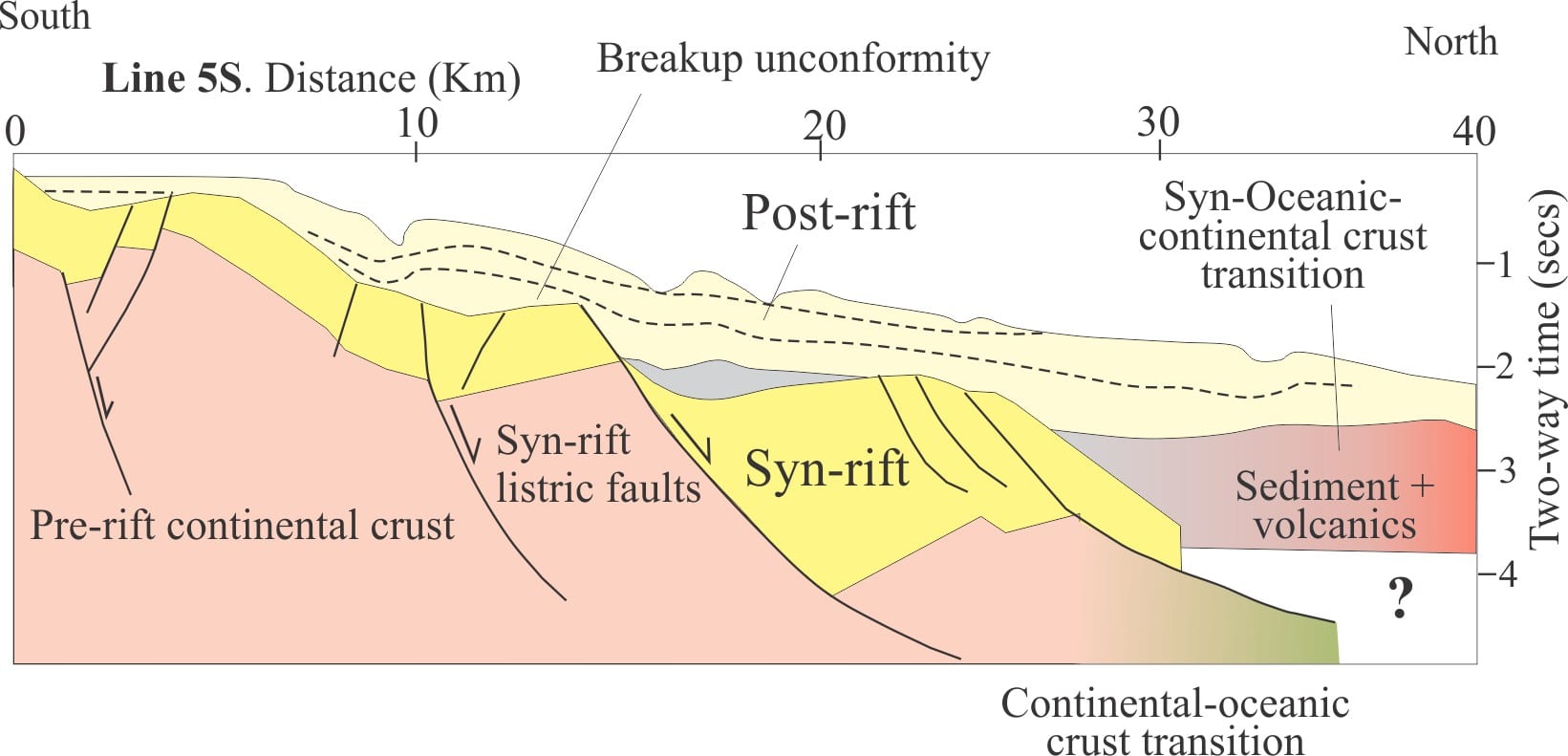
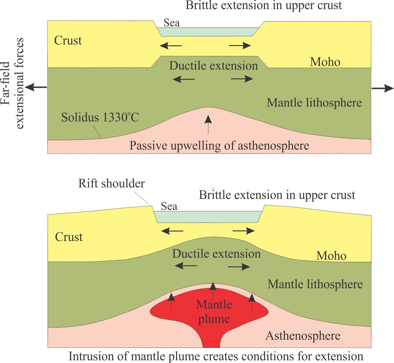
Sedimentary basins: Stretching the lithosphere: Rift basins

Two primary mechanisms of continental rifting: Passive rifting where mantle passively upwells in (isostatic) response to crustal stretching and thinning; Active rifting where the stretching is a consequence of a rising mantle plume. Modified from Allen and Allen, 2005, Fig. 3.10.


Glossary of geological terms.


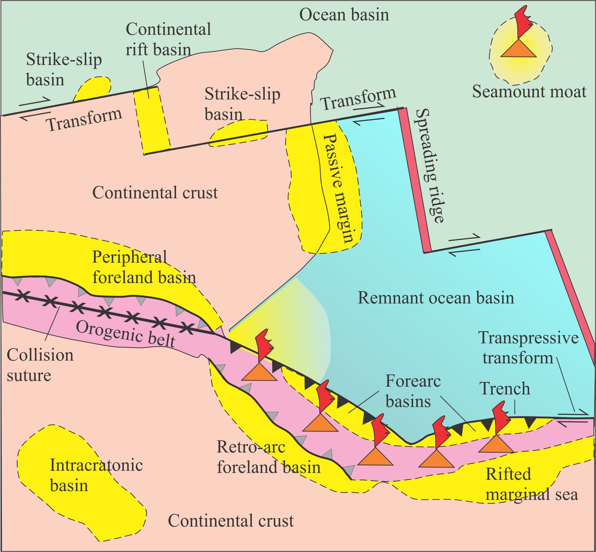
Sedimentary basins: Classification of sedimentary basins

A schematic of sedimentary basins distributed across three continental blocks, an ocean basin (e.g. Pacific basin), and a remnant ocean basin (e.g. Juan de Fuca plate). Key tectonic elements are: subduction zones (black triangles) and associated basins, an orogenic thrust belt resulting from continent-continent or terrane-terrane collision (e.g. Alberta foreland basin) and associated unroofing of a metamorphic core complex (e.g. Omineca Belt, Canadian Rockies), an orogenic belt in the plate above a subduction zone associated with a volcanic arc, continental rifting with a nascent rift basin (e.g. Red Sea), and a much older passive margin sedimentary prism (east coast North America), ocean crust rifting at spreading ridges, basins associated with transform faults, and intracratonic (e.g. modern Hudson Bay) and intra-oceanic basins, the latter depicted as a moat around large sea mounts (e.g. Hawaii). Figure is modified from Ingersoll (1988) who modified it from Dickinson (1980).

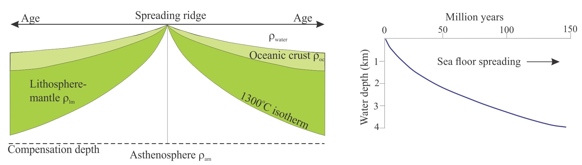
Sedimentary basins: The thermal structure of the lithosphere

Oceanic lithosphere increases in density and thickness as a function of age, cooling and distance from the spreading ridge. To maintain isostatic balance, ocean water depth must also increase. Modified from Allen and Allen, 2005, Figs 2.16, 2.19, 2.20.

Sedimentary basins    Isostasy: A lithospheric balancing act

Raised gravel beach ridges resulting from glacio-isostatic rebound following melting of the Laurentide Icesheet. Belcher Islands. The distance between the yellow dots is 500 m. Modern beach is on the left.

Sedimentary basins:   Regions of prolonged subsidence

Modern sedimentary basin fill – the Namib dune sea (Namibia), where dunes as high as 300-400m border a salt flat and ephemeral streams. About 50 km east of the Atlantic coast. Image credit: USGS, Landsat 8


Sedimentary basins    Defining the lithosphere

Typical yield strength envelopes for two sets of conditions in the upper 60 km of continental lithosphere: Left – strong, dry lower crust and mantle lithosphere, where strength is distributed with depth; Right – weak and wet lower crust and mantle lithosphere, where most of the strength is in the upper, brittle crust. Conditions within each envelope promote an elastic response. Beyond the envelopes the response to deformation is ductile. Strength increases to the right. Modified from Allen and Allen, 2013, Fig 2.38.


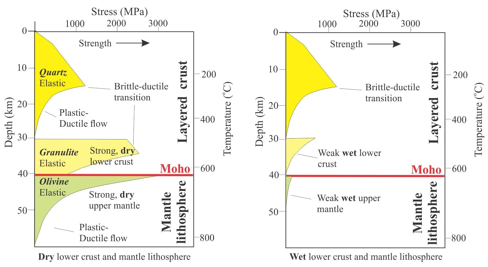
Sedimentary basins   The rheology of the lithosphere

Typical yield strength envelopes for two sets of conditions in the upper 60 km of continental lithosphere: Left – strong, dry lower crust and mantle lithosphere, where strength is distributed with depth; Right – weak and wet lower crust and mantle lithosphere, where most of the strength is in the upper, brittle crust. Conditions within each envelope promote an elastic response. Beyond the envelopes the response to deformation is ductile. Strength increases to the right. Modified from Allen and Allen, 2013, Fig 2.38.

Sequence stratigraphy   Which sequence stratigraphic model is that?

Sequence stratigraphy   Depositional systems and systems tracts

An idealised panorama of depositional systems across terrestrial and marine environments.

Sequence stratigraphy   Stratigraphic condensation – condensed sections


Sequence stratigraphy  Stratigraphic lapouts

Sequence stratigraphy    Clinoforms and clinothems

Sequence stratigraphy  Stratigraphic trends and stacking patterns

Retrogradational stacking, Strand Bay Fm.

Sequence stratigraphy   Shorelines and shoreline trajectories

Sequence stratigraphy   Parasequences

Sequence stratigraphy   Sequence stratigraphic surfaces

Sequence stratigraphy   Stratigraphic cycles: What are they?

Sequence stratigraphy  Autogenic or allogenic dynamics in stratigraphy?

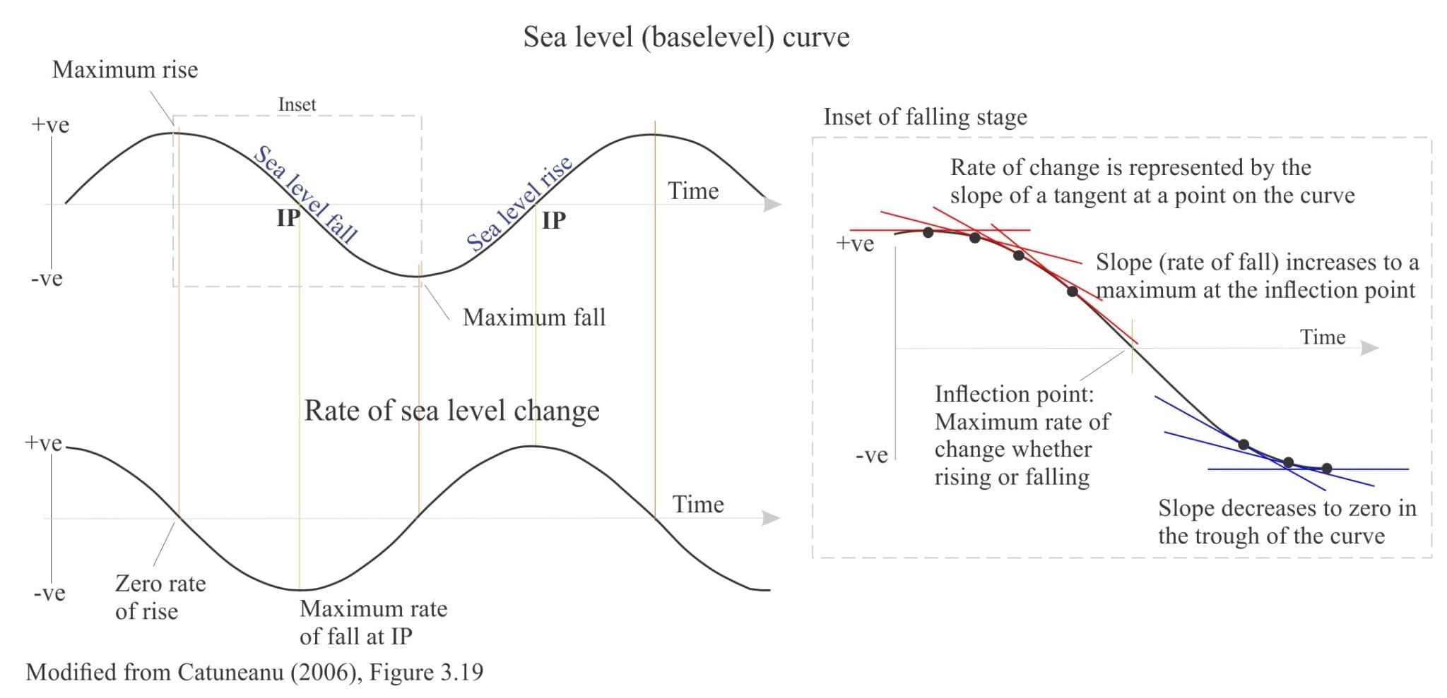
Sequence stratigraphy   How to read a sea level curve

Compnents of a sea level curve and an example of tangents to the curve

Sequence stratigraphy   Facies and facies models

three Facies models for turbidites

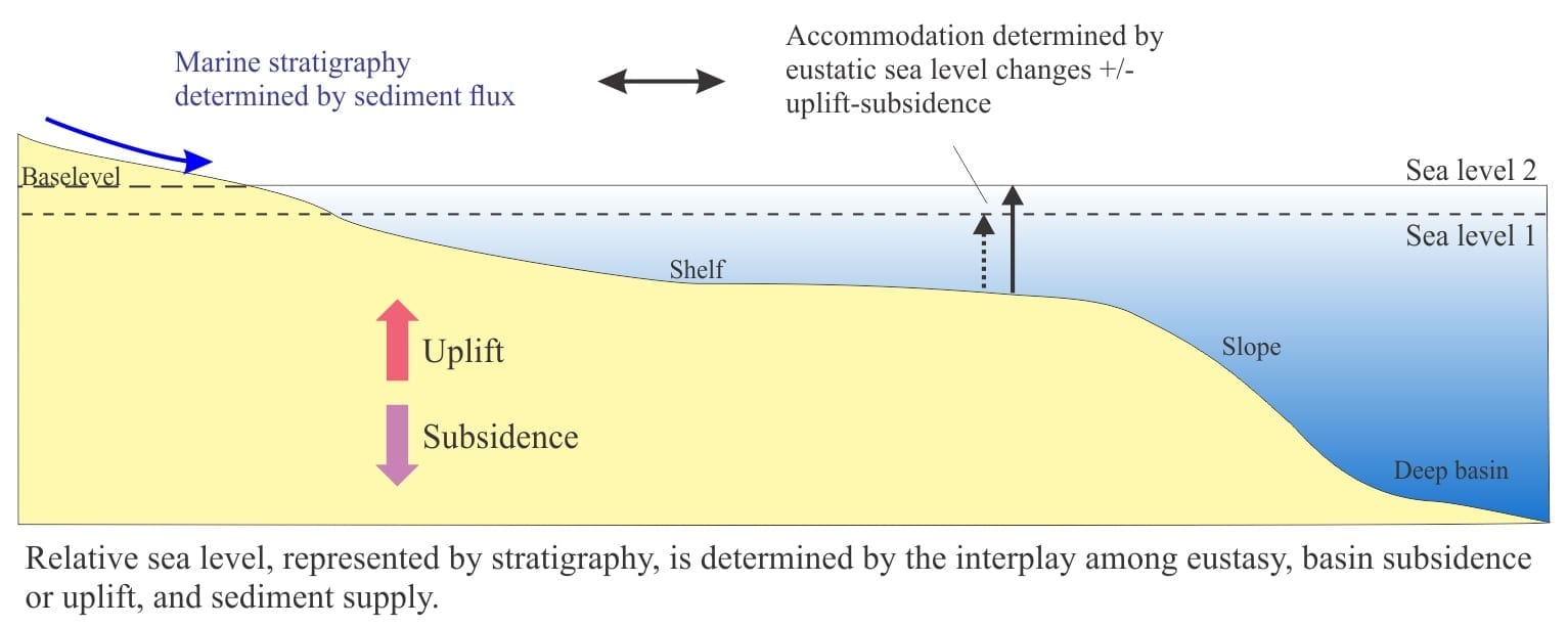
Sequence stratigraphy   Sediment accommodation and supply

Diagram showing accommodation space

Sequence stratigraphy   Baselevel, Base-level, and Base level

Sequence stratigraphy   A timeline of stratigraphic principles; 15th to 18th C

Sequence stratigraphy  A timeline of stratigraphic principles; 19th C to 1950

Sequence stratigraphy   A timeline of stratigraphic principles; 1950-1977


Volcanics in outcrop: Pyroclastic fall deposits

Pliocene airfall tephras, Karioi, NZ

Mineralogy of carbonates: Stromatolite reefs

Stromatolite reef mounds

Sedimentary structures: Stromatolites

Exhumed stromatolite domes

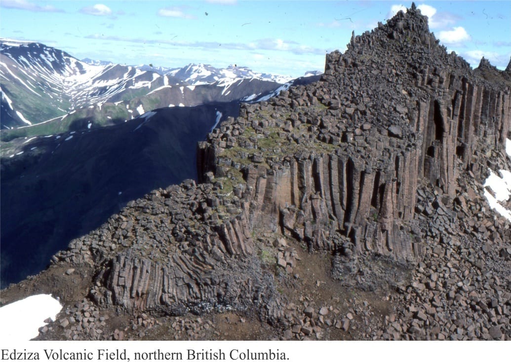
Volcanics in outcrop: Secondary volcaniclastics

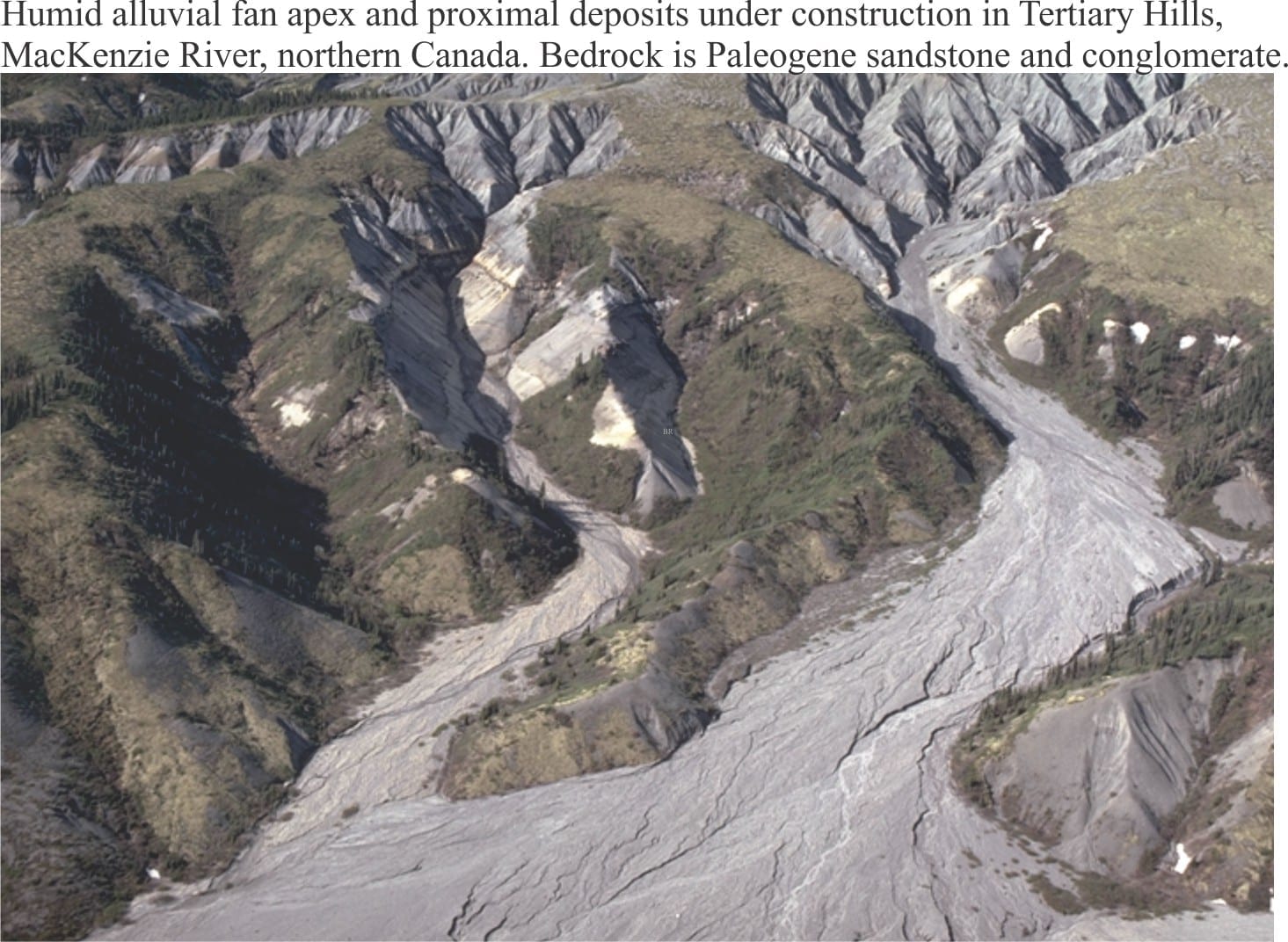
Sedimentary structures: Alluvial fans

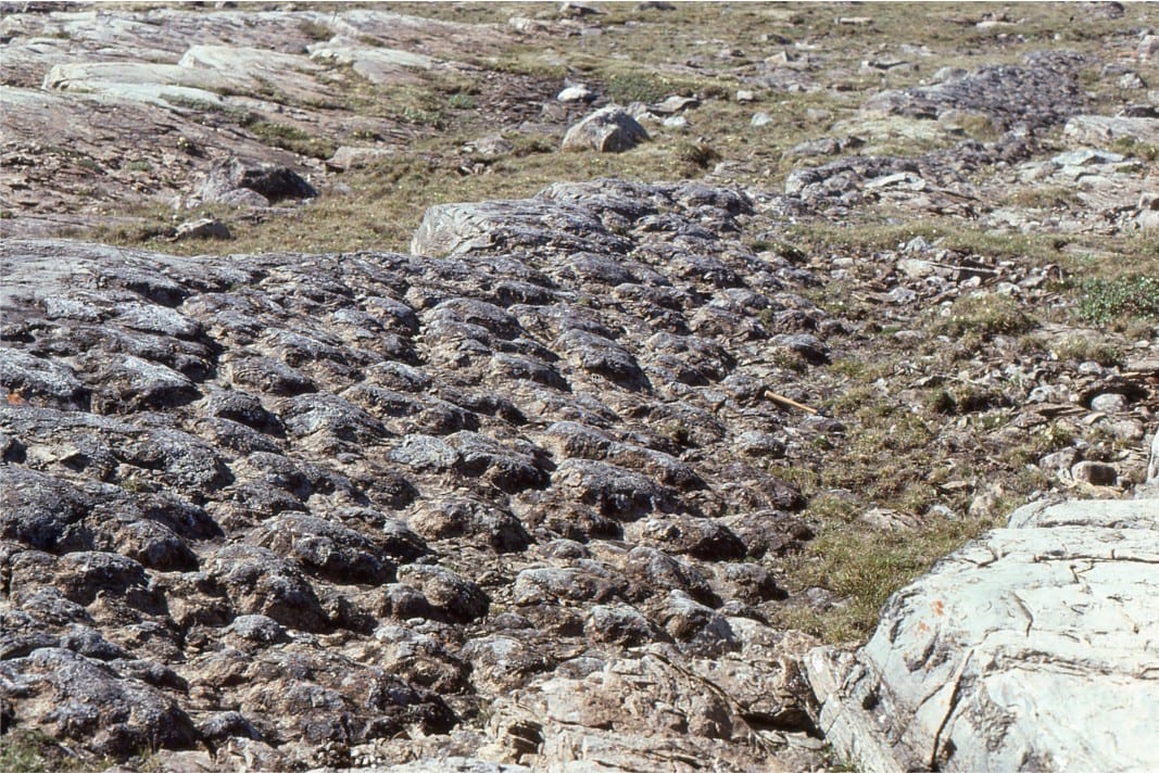
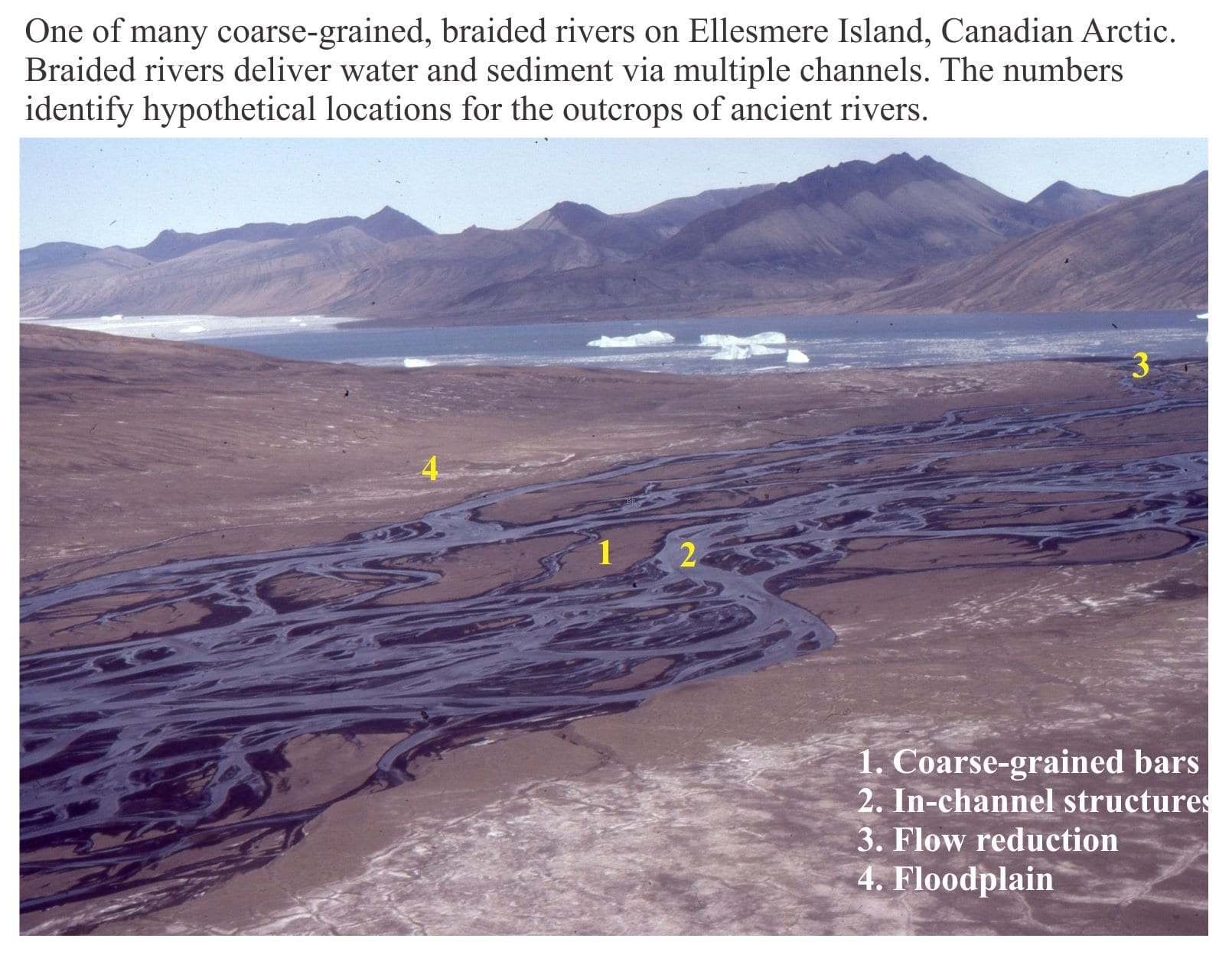
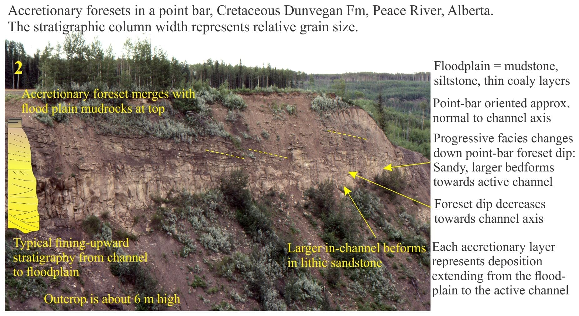
Sedimentary structures: coarse-grained fluvial

Sedimentary structures: Fine-grained fluvial

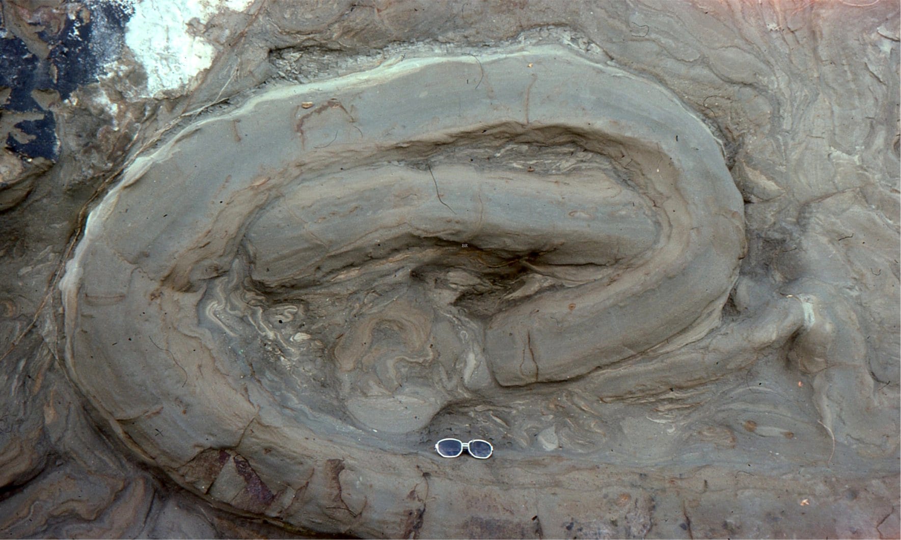
Sedimentary structures: Mass transport deposits

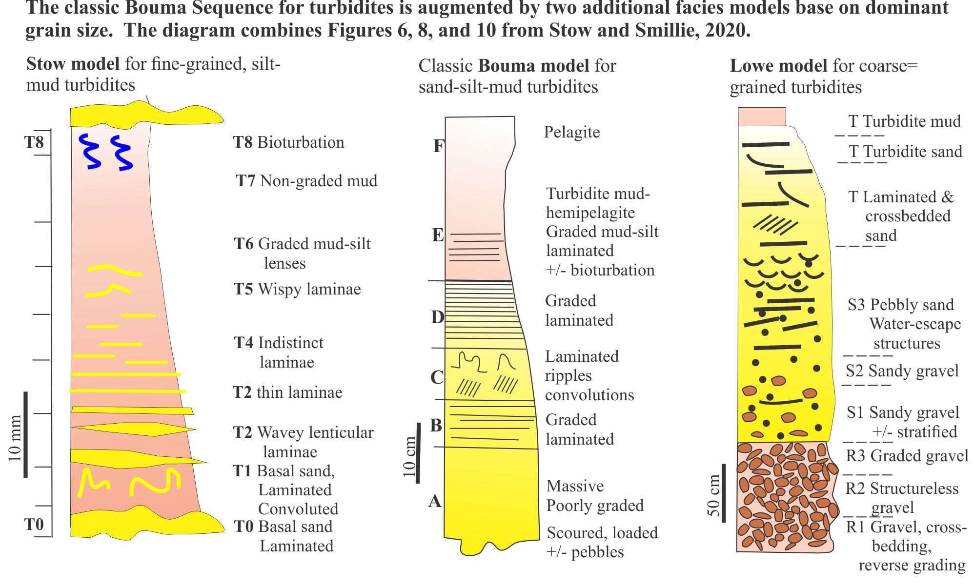
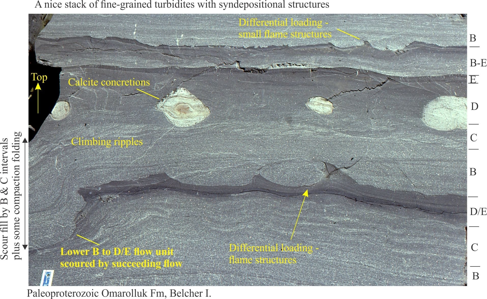
Sedimentary structures: Turbidites

Sedimentary structures: Shallow marine

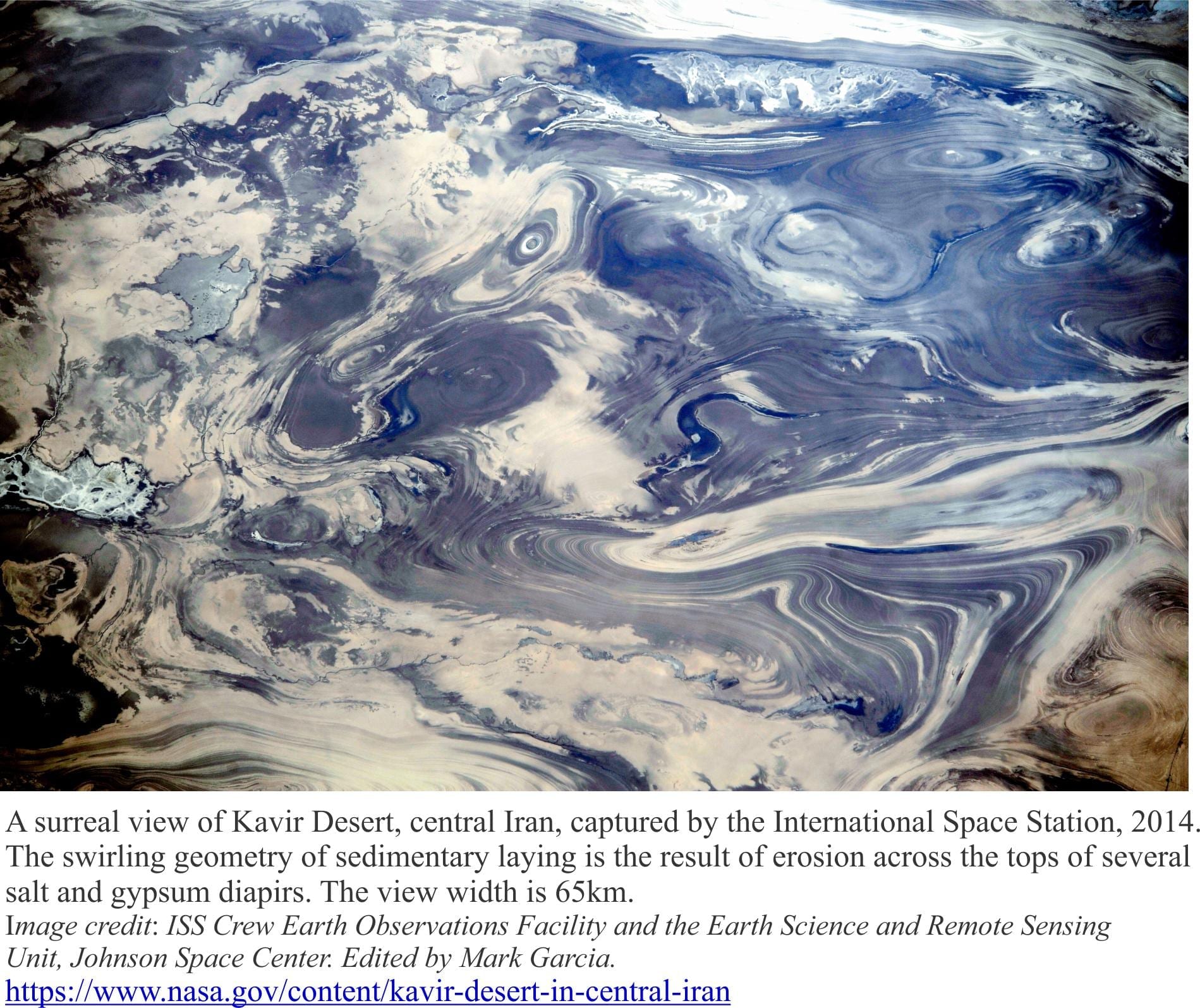
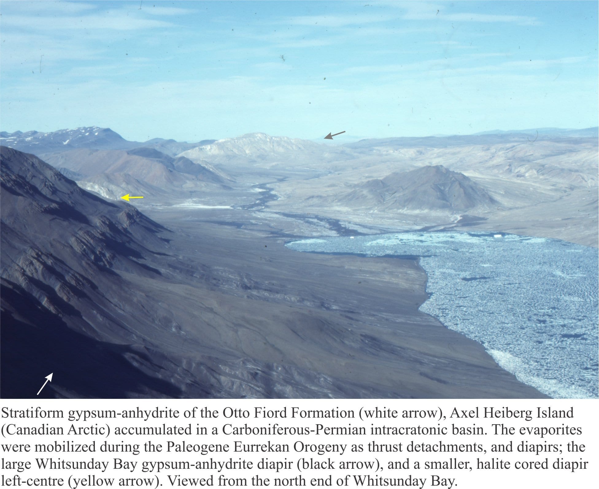
Mineralogy of evaporites: the rise of diapirs

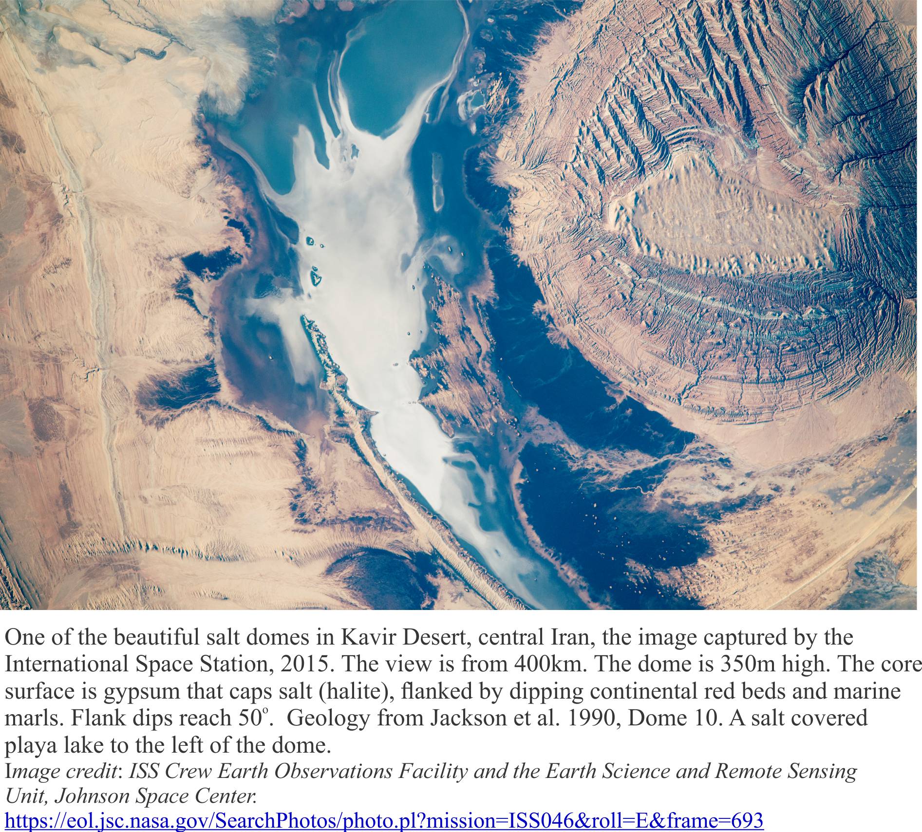
Mineralogy of evaporites: salt tectonics

Mineralogy of evaporites: Marine basins

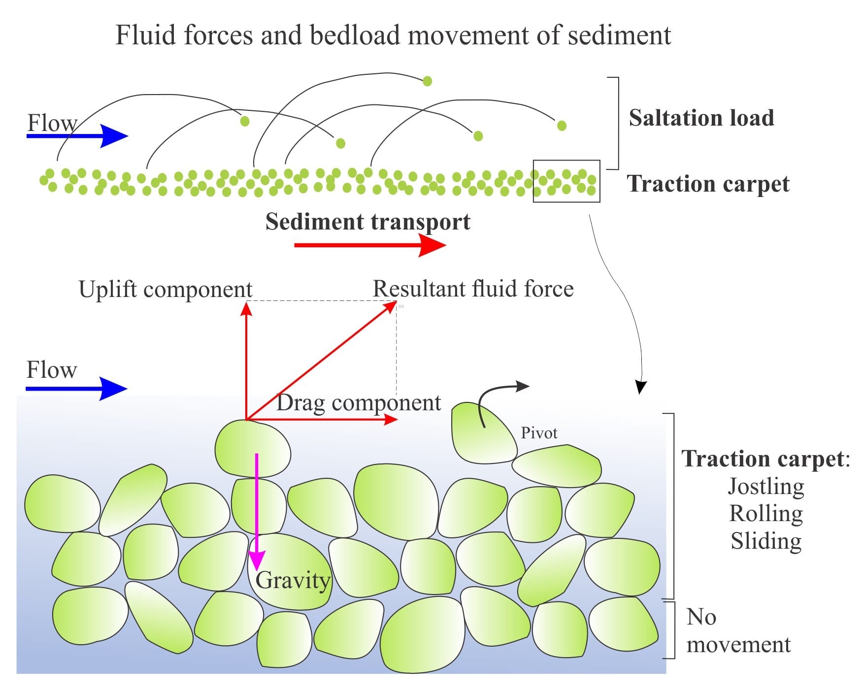
Sediment transport: Bedload and suspension load

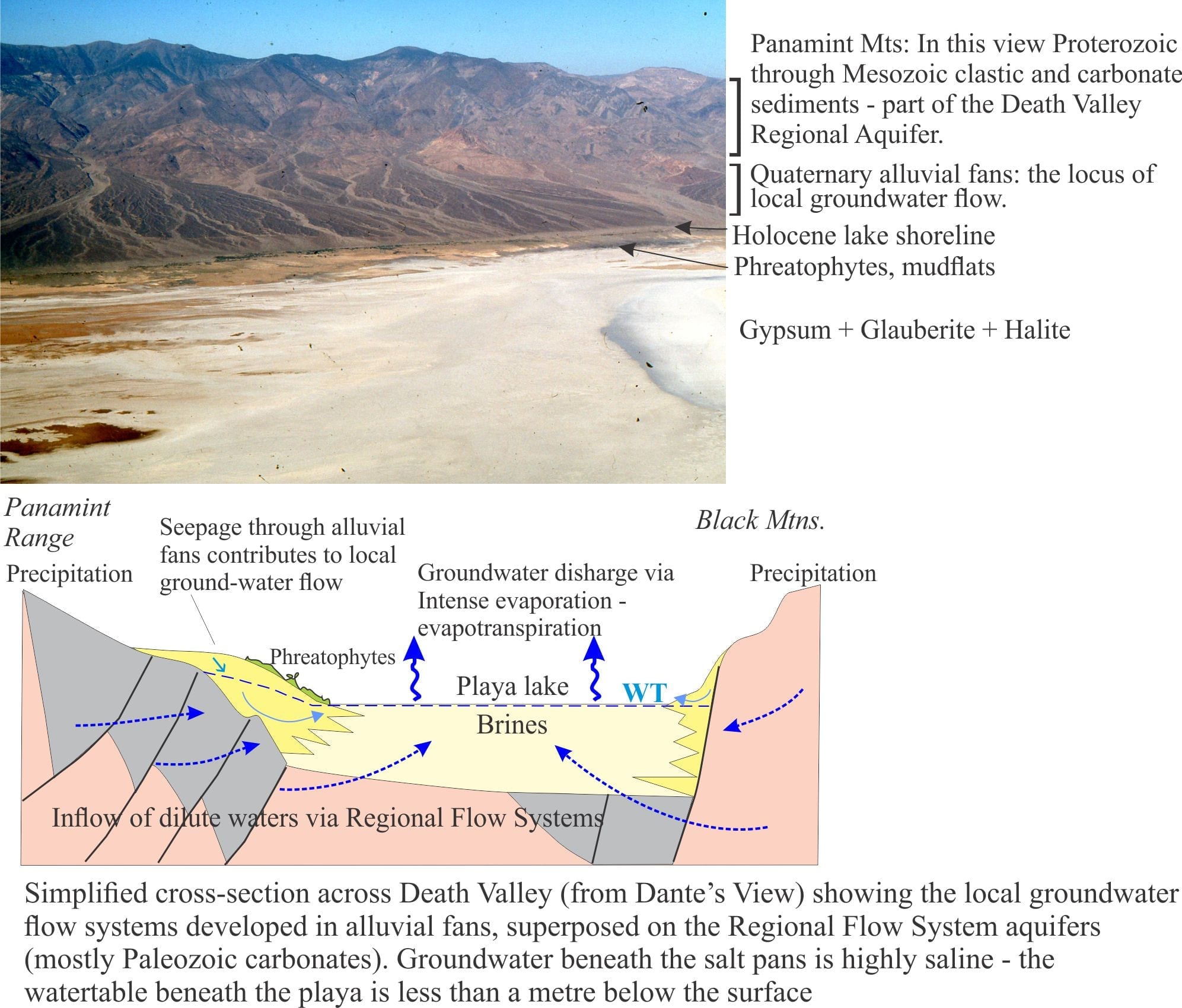
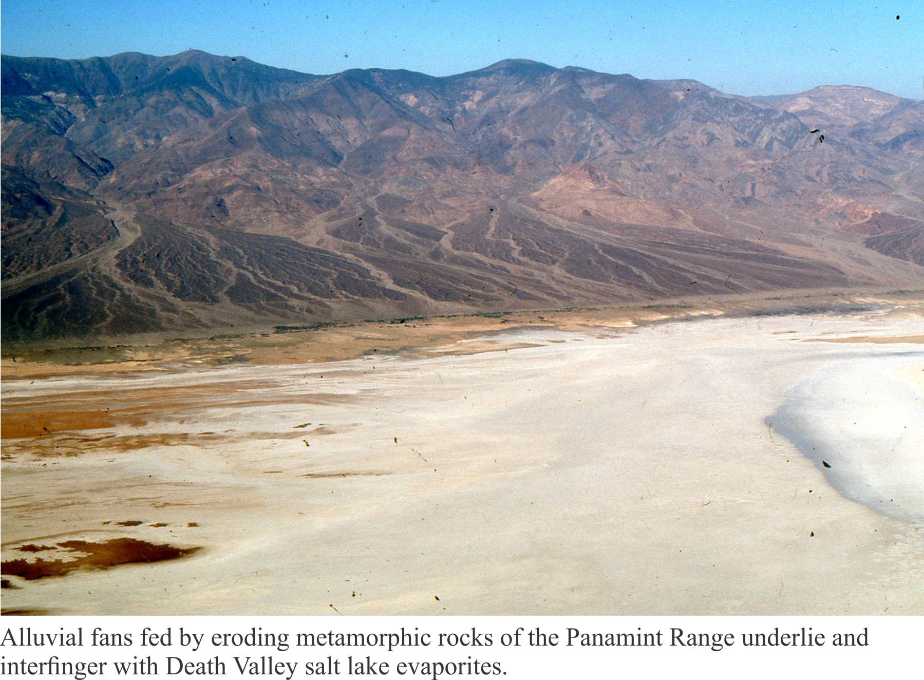
Mineralogy of evaporites: Death Valley hydrology

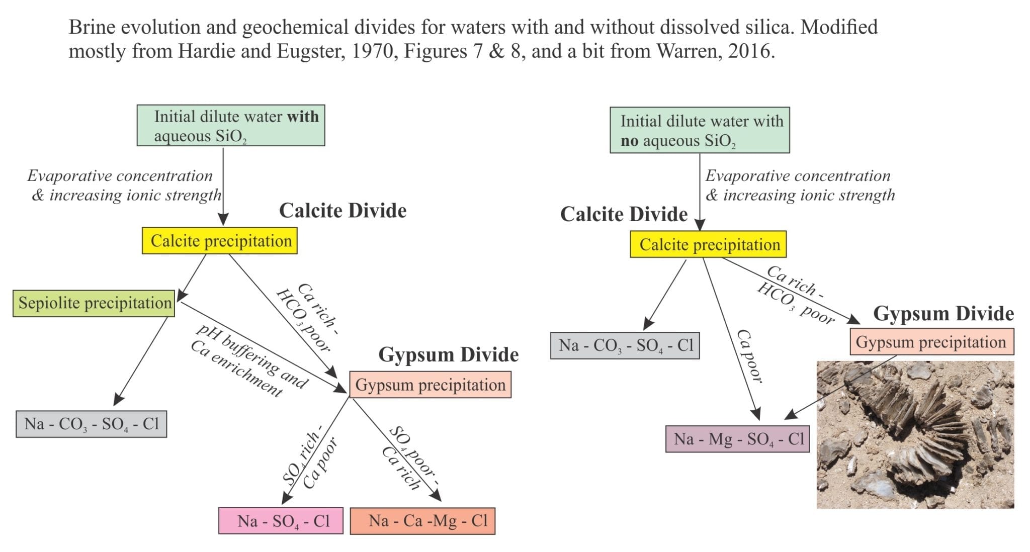
Mineralogy of evaporites: Saline lake brines

Mineralogy of evaporites: Saline lakes

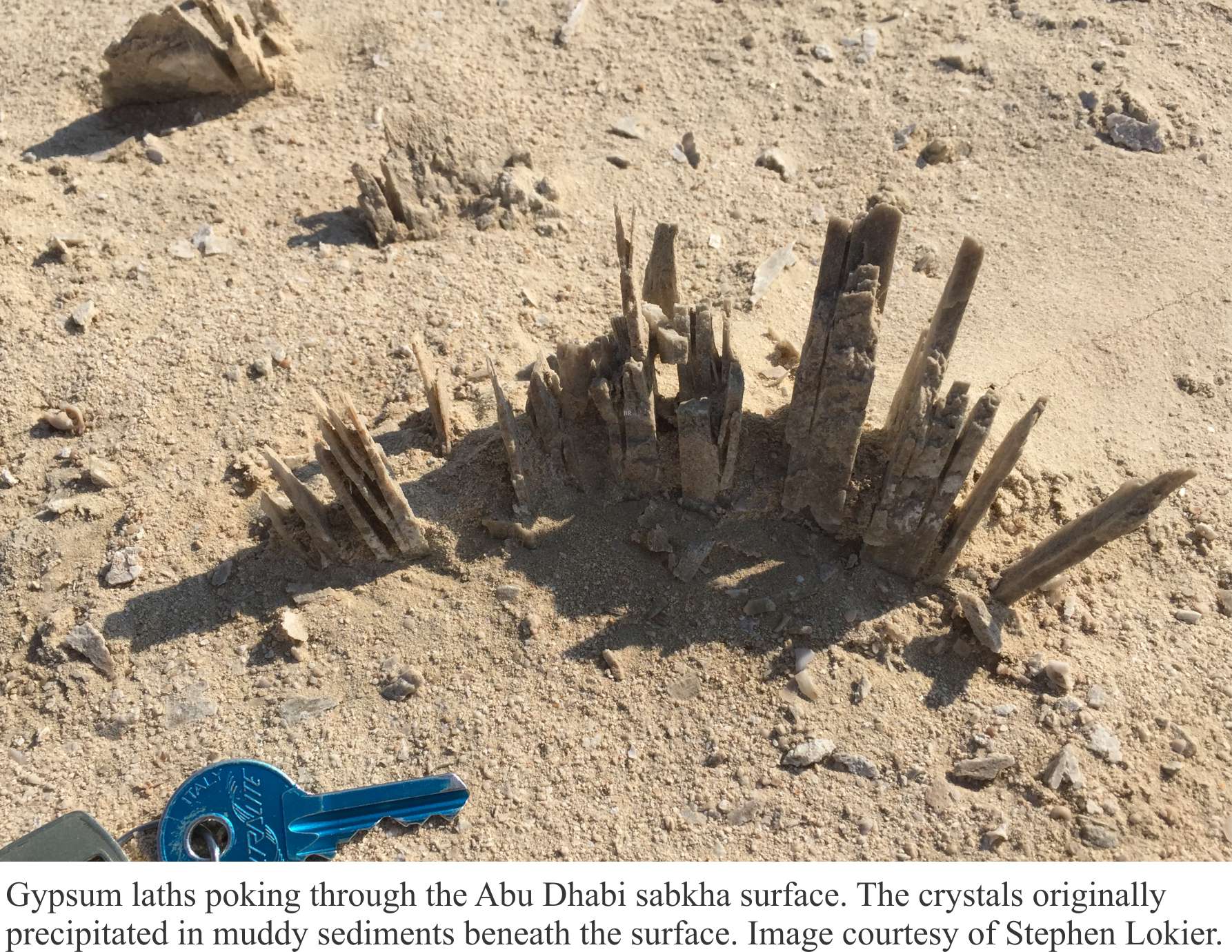
Mineralogy of carbonates; Sabkhas

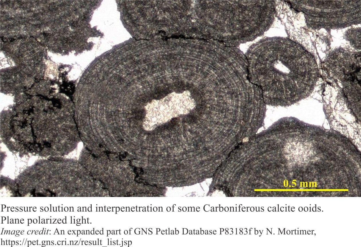
Mineralogy of carbonates; Pressure solution

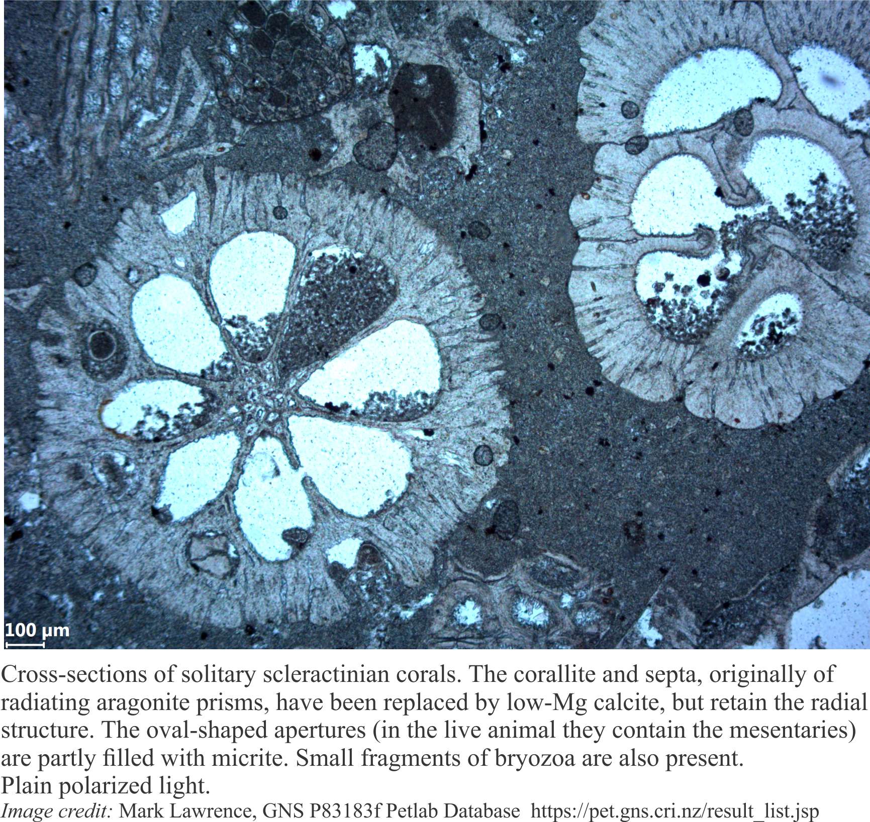
Mineralogy of carbonates; Neomorphism

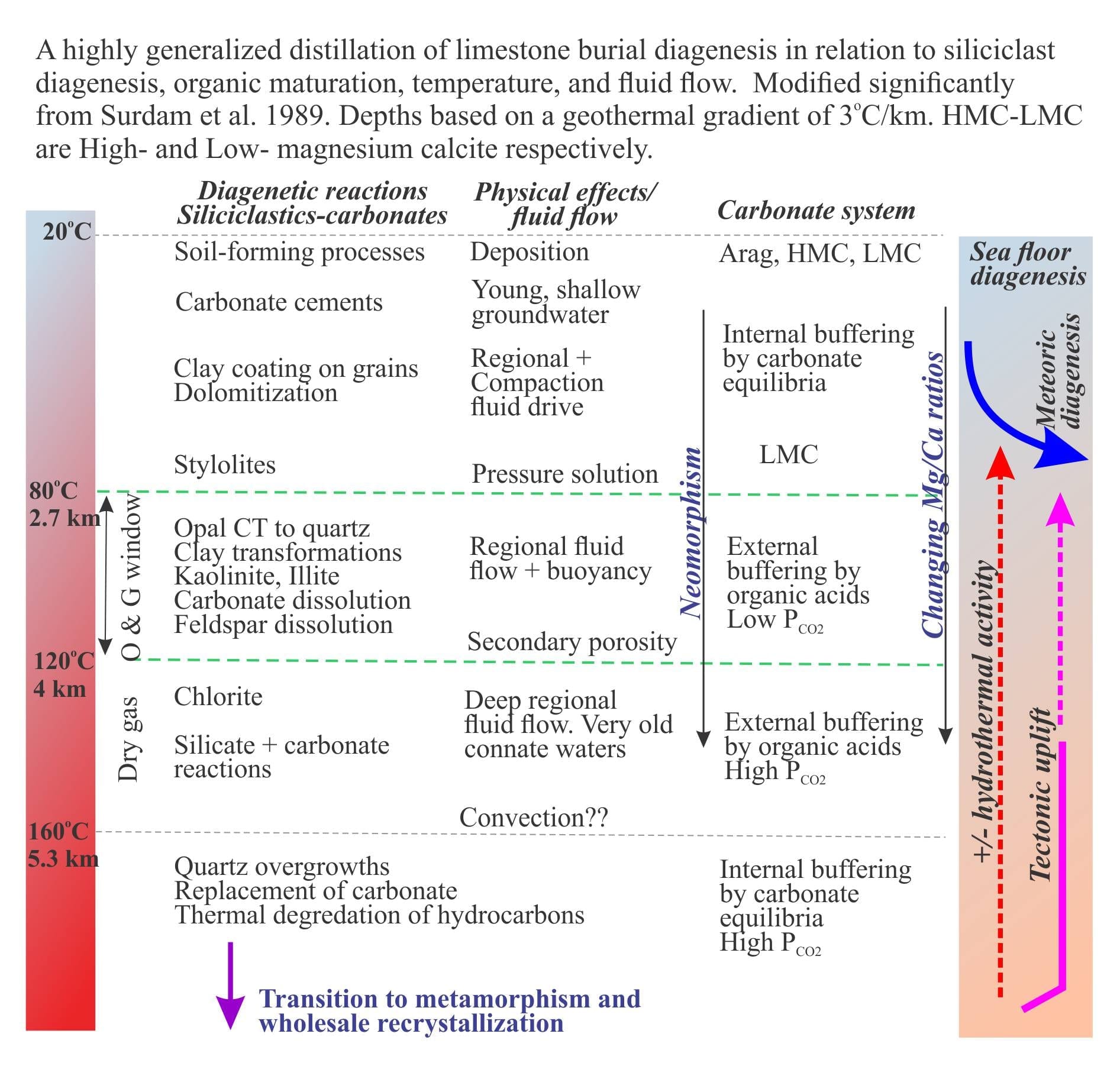
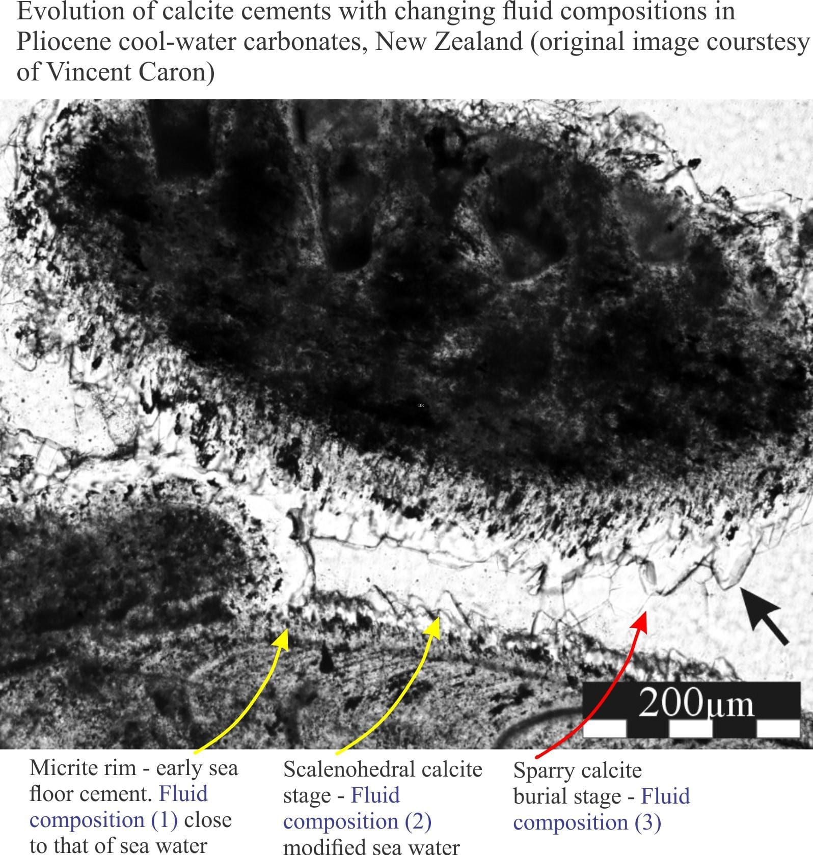
Mineralogy of carbonates; Burial diagenesis

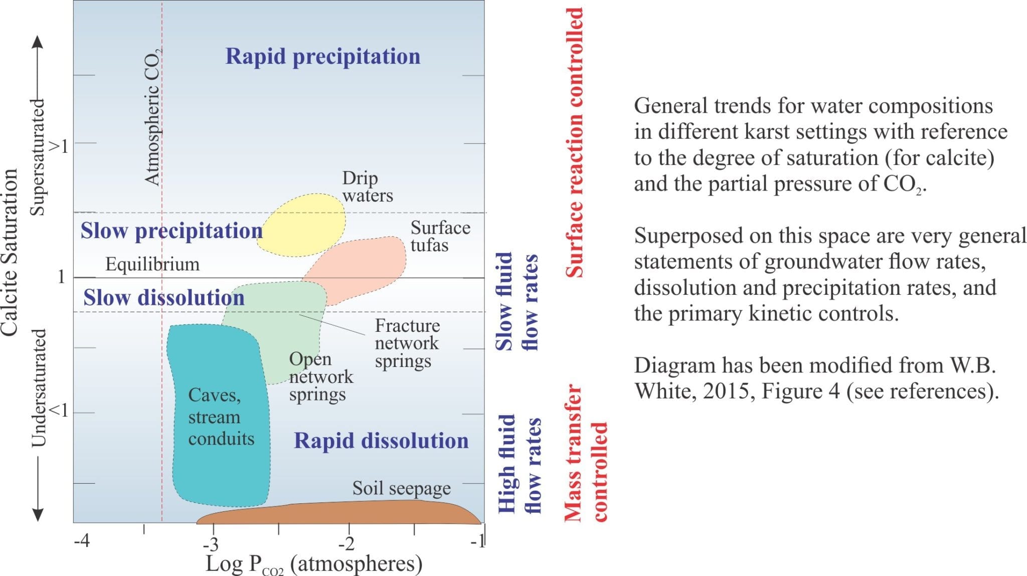
Mineralogy of carbonates; Karst


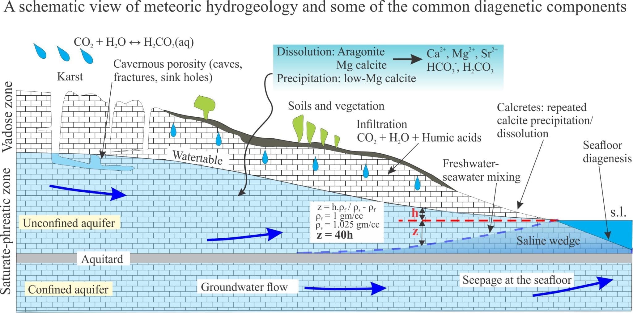
Mineralogy of carbonates; meteoric hydrogeology

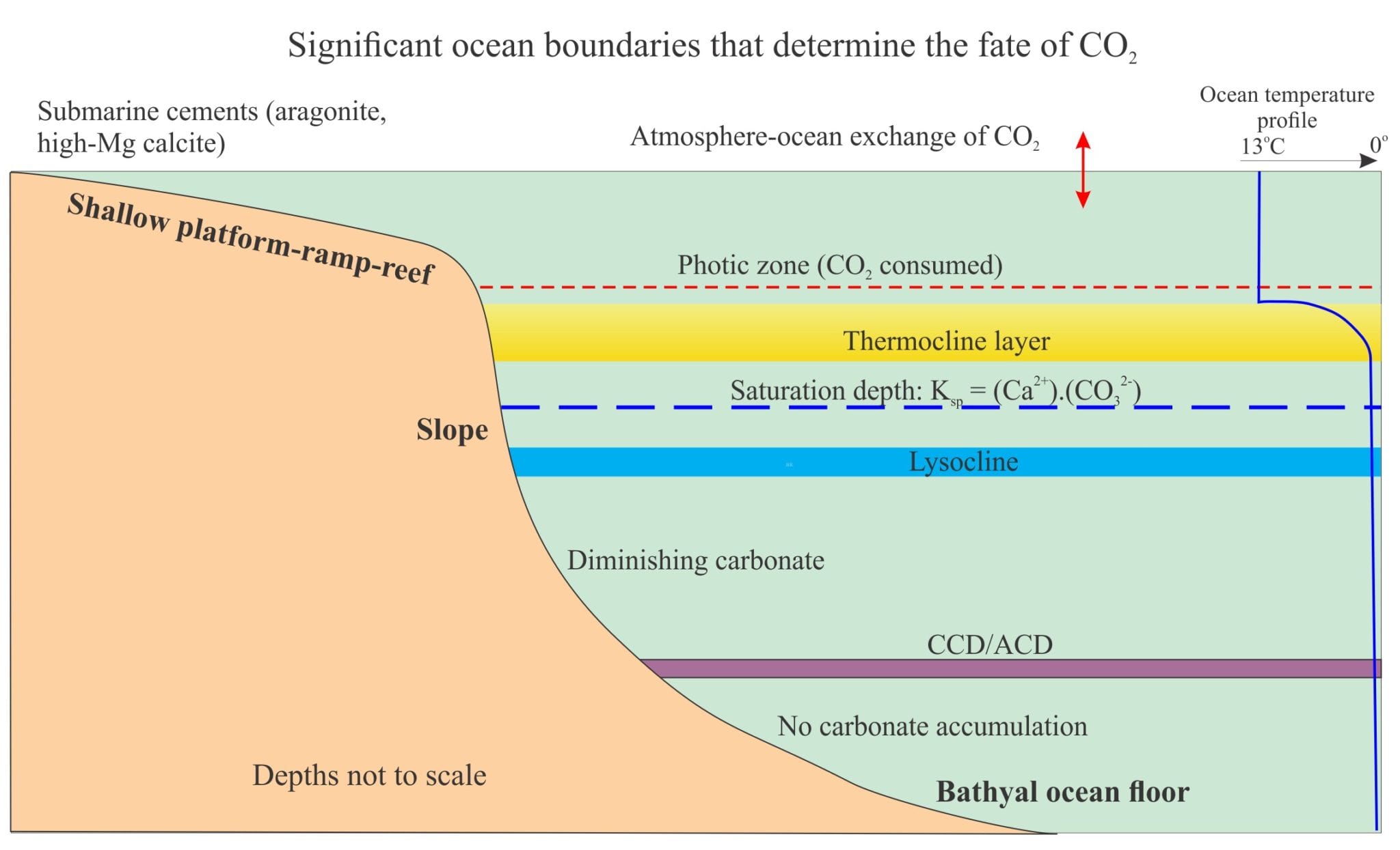
Mineralogy of carbonates; deep sea diagenesis

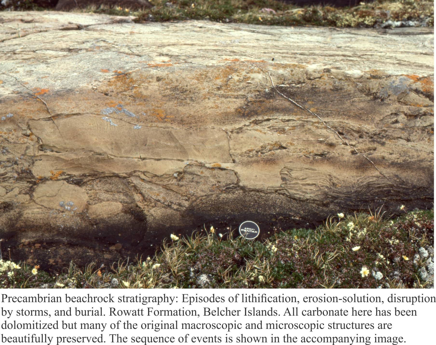
Mineralogy of carbonates; beachrock

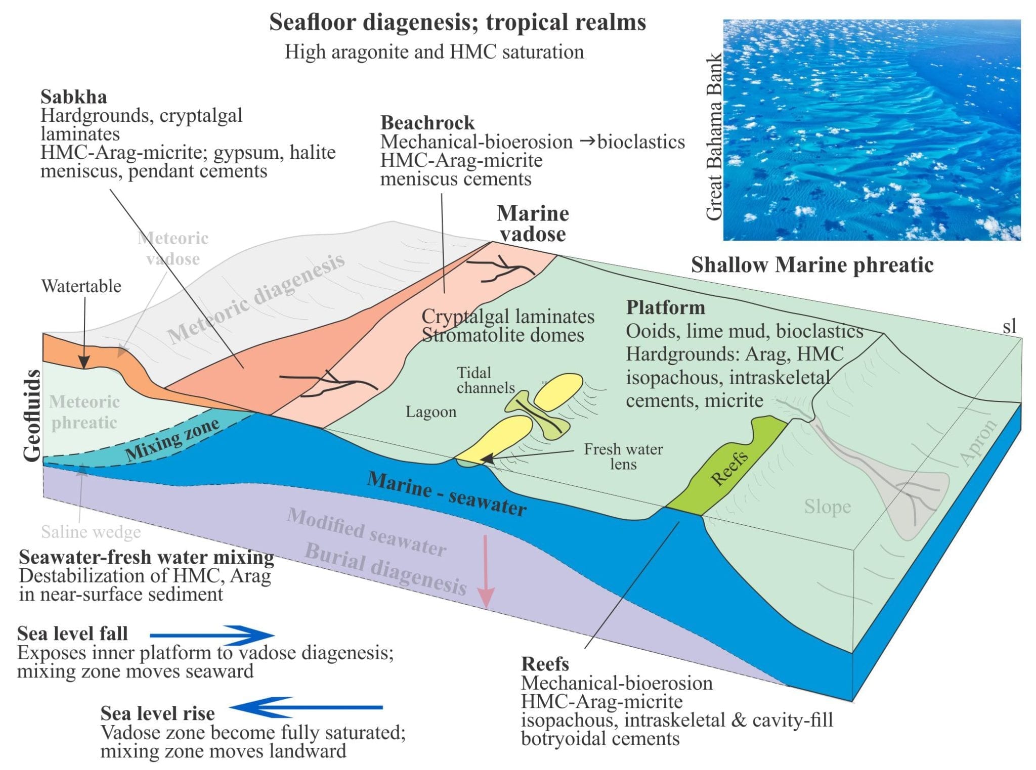
How to … Mineralogy of carbonates; sea floor diagenesis

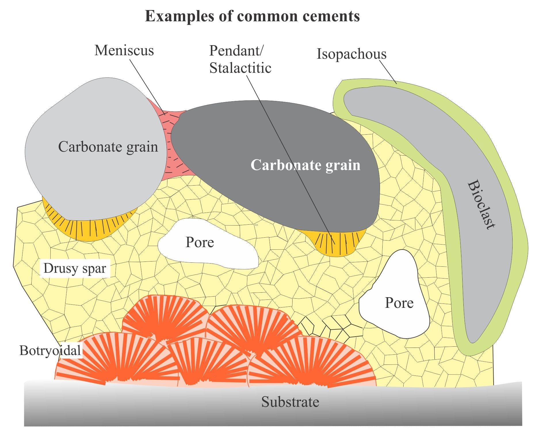
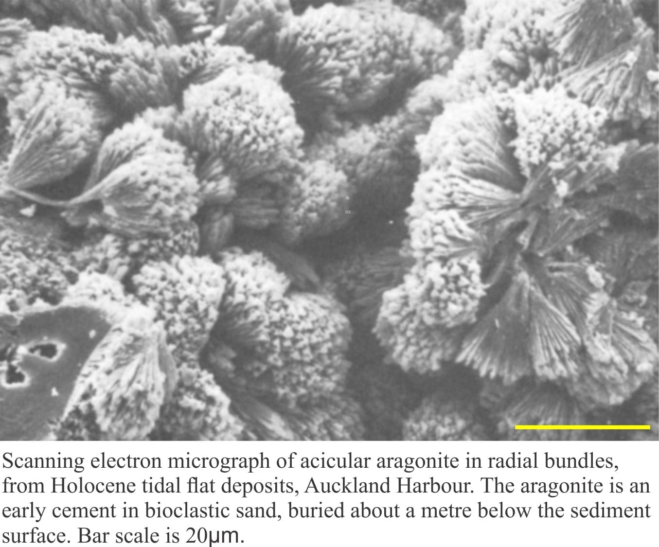
Mineralogy of carbonates; cements

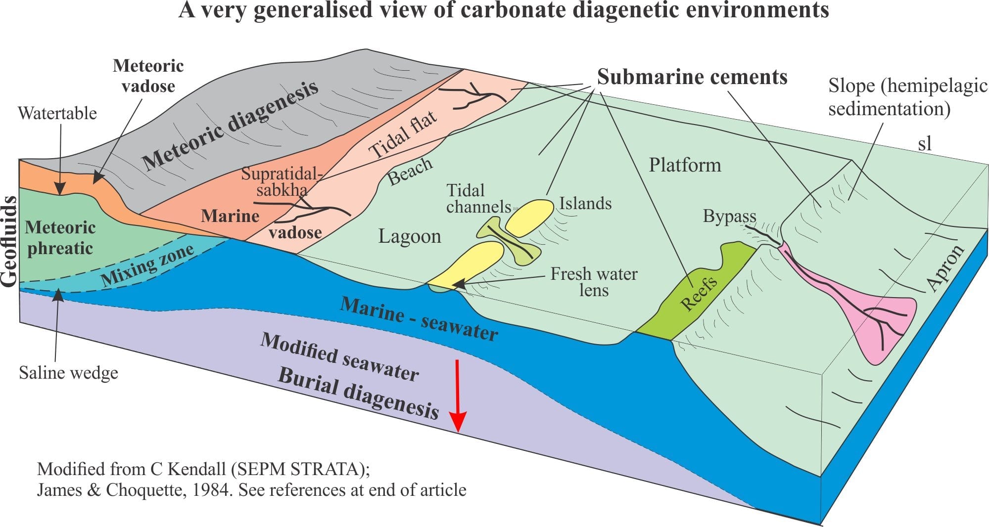
Mineralogy of carbonates; diagenetic settings


How to… Mineralogy of carbonates; basic geochemistry

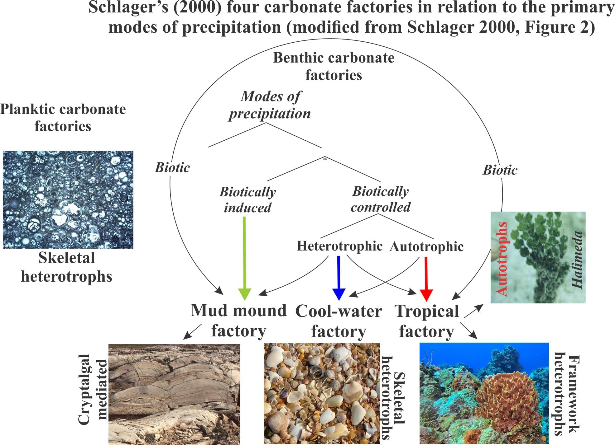
How to… Mineralogy of carbonates; carbonate factories

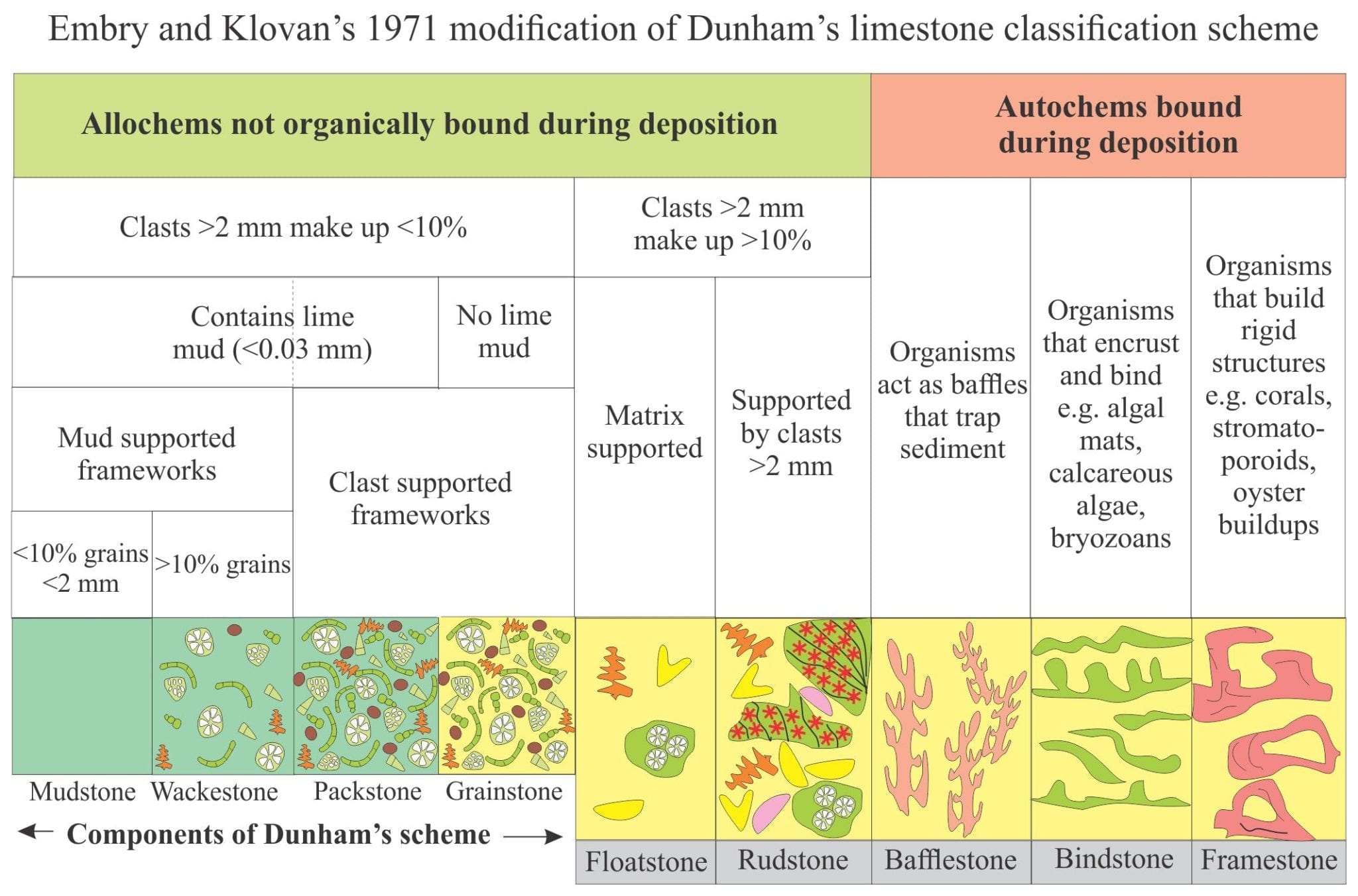
How to… Mineralogy of carbonates; classification

How to… Mineralogy of carbonates

How to… Mineralogy of carbonates; skeletal grains

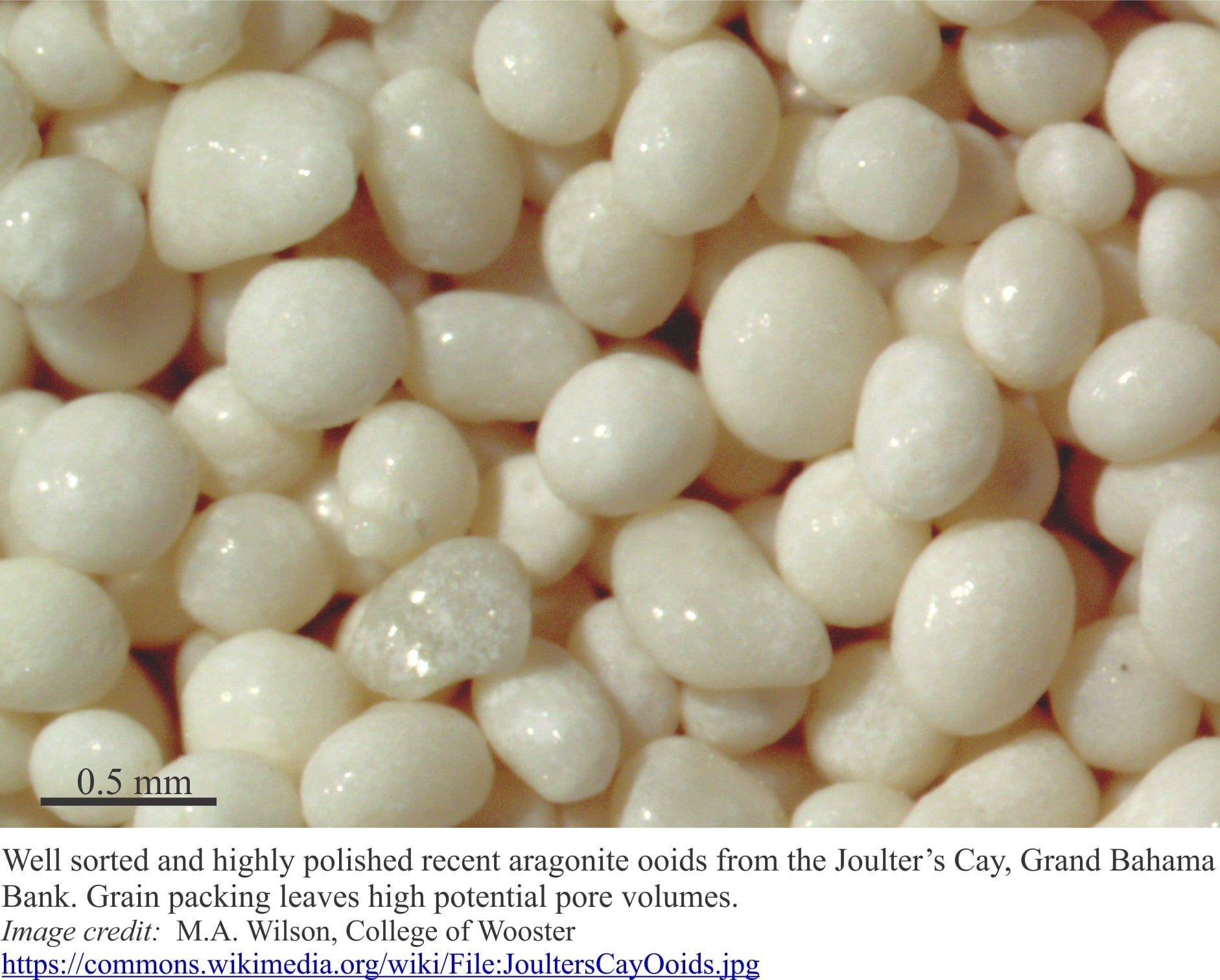
How to… Mineralogy of carbonates; non-skeletal grains

How to… Mineralogy of carbonates; lime mud


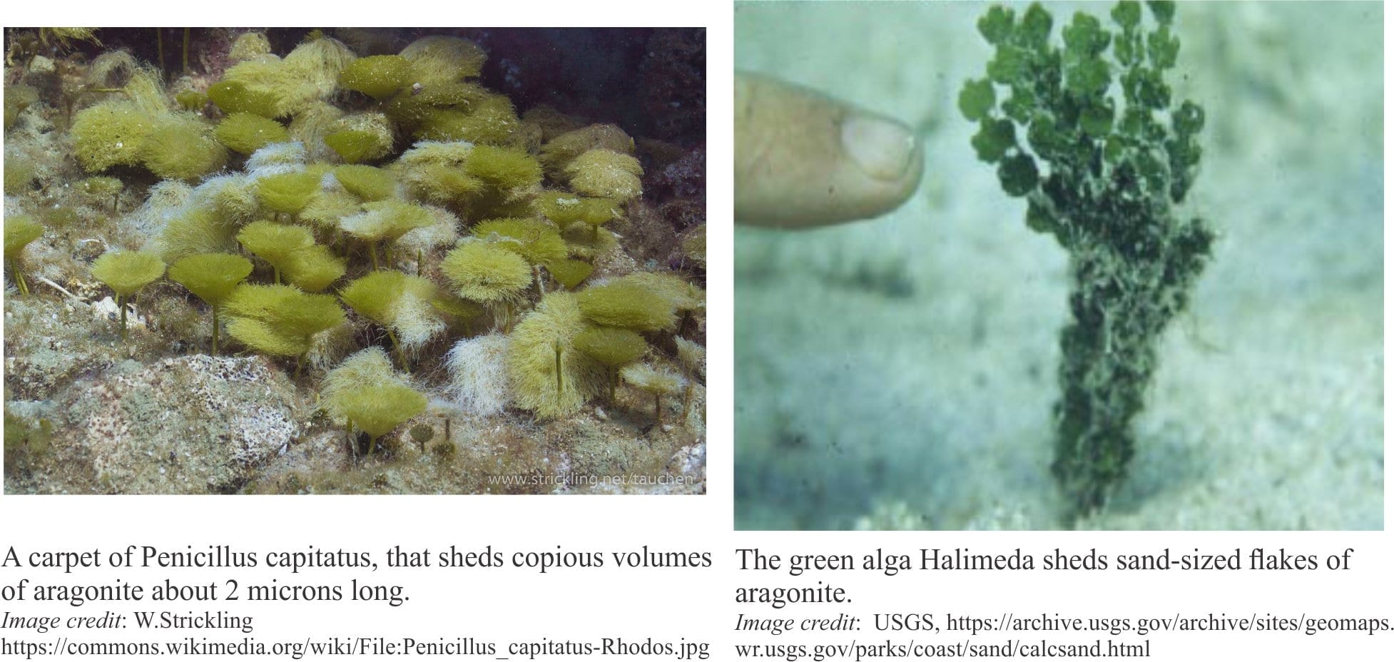
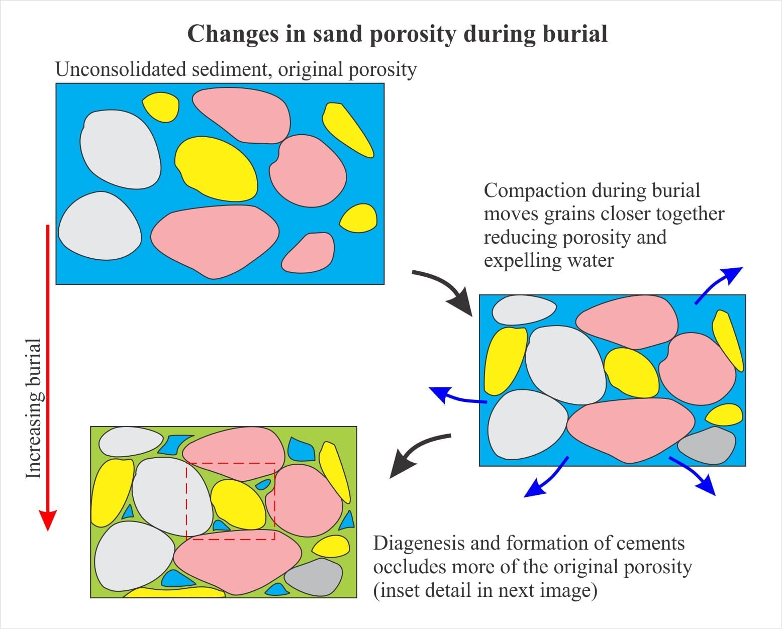
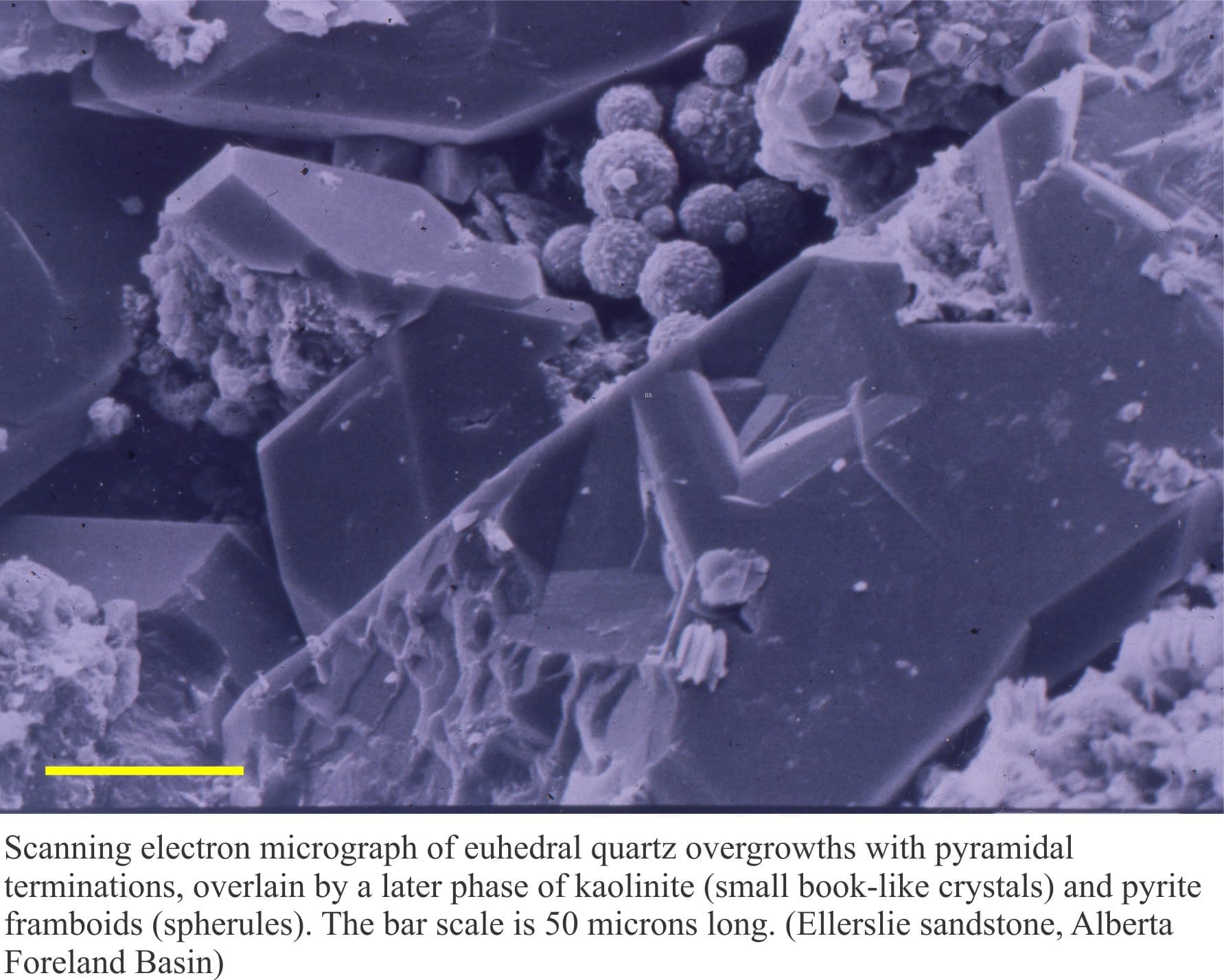
The mineralogy of sandstones: porosity and permeability

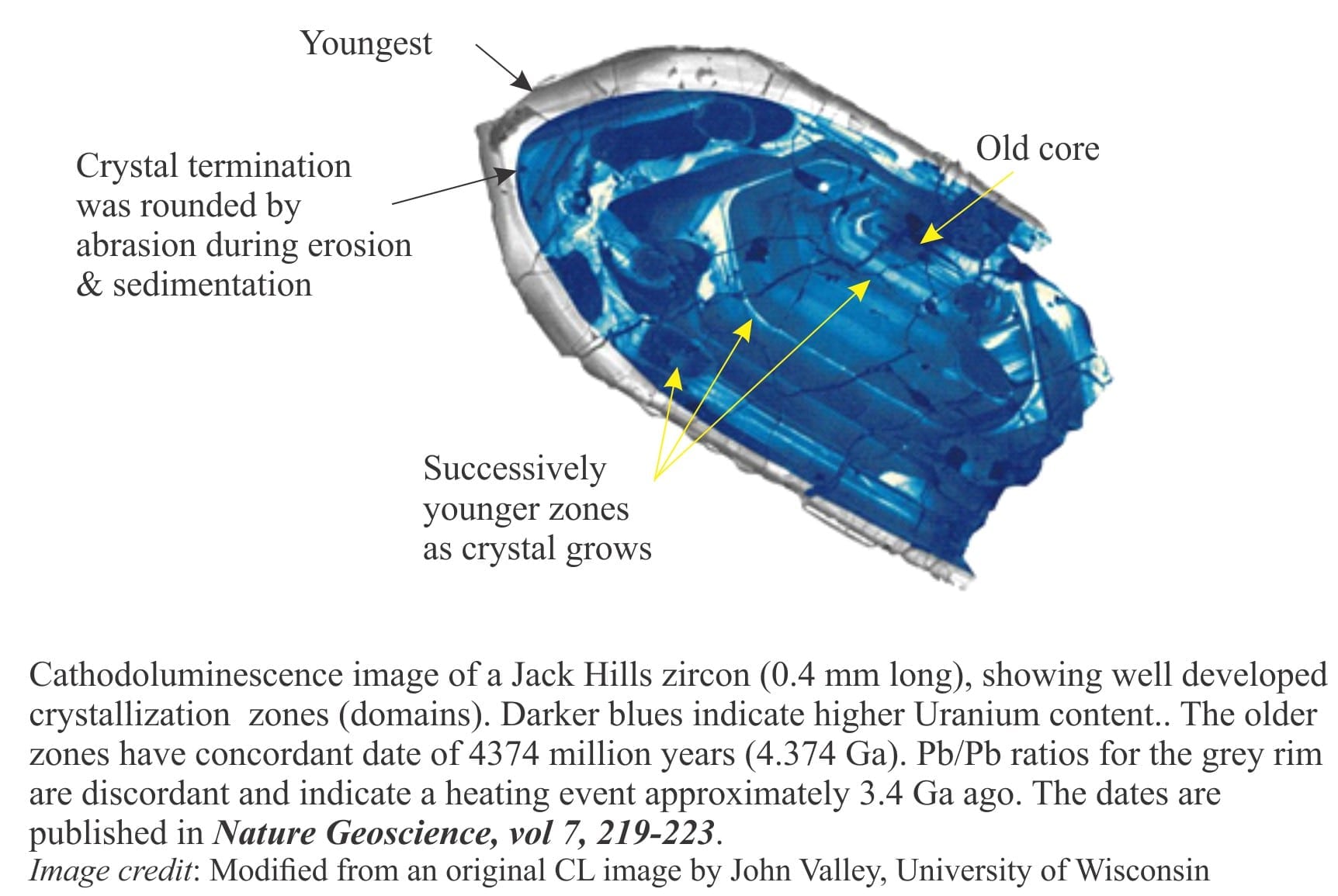
How to… The provenance of detrital zircon

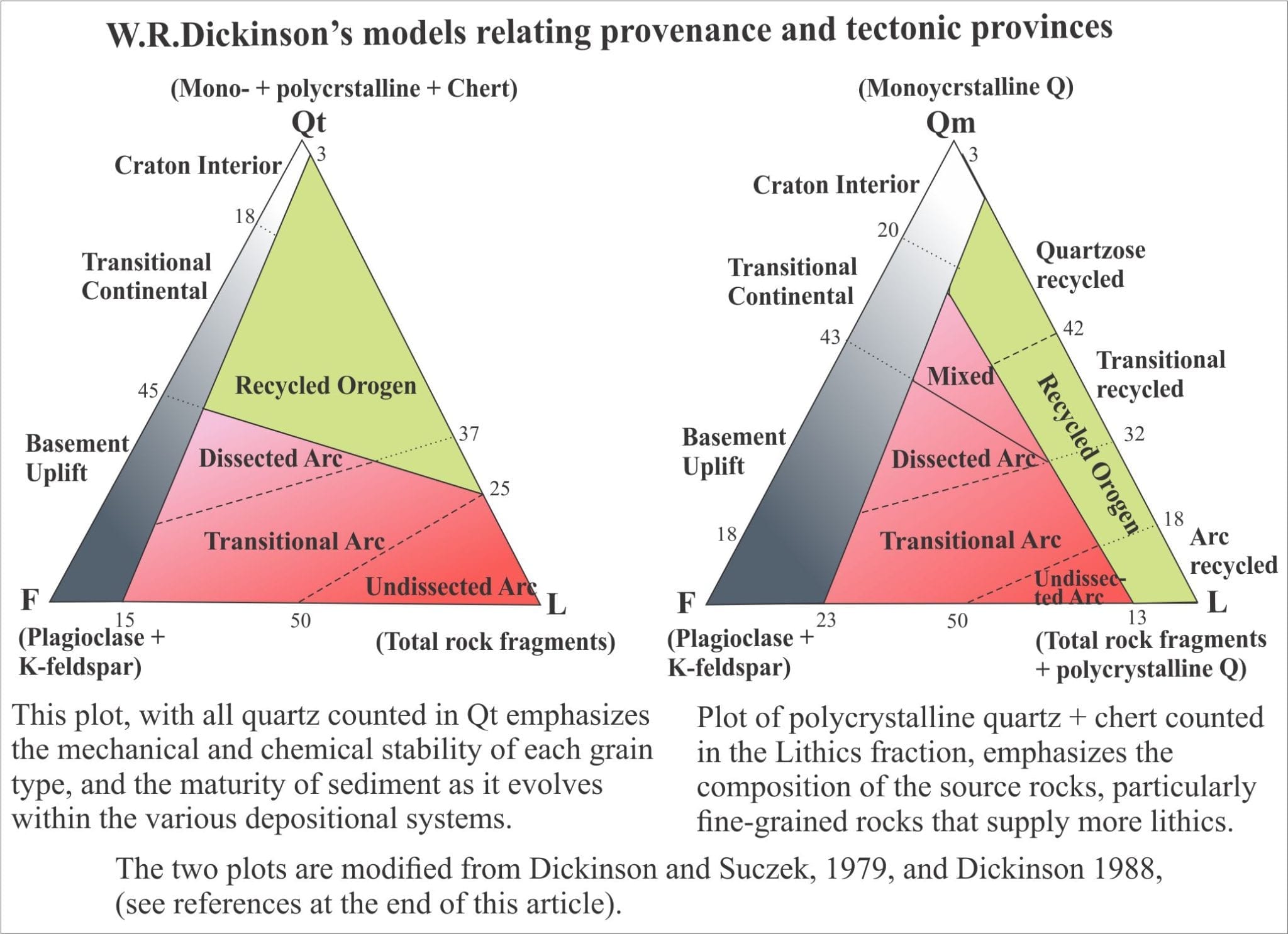
How to… Provenance and plate tectonics

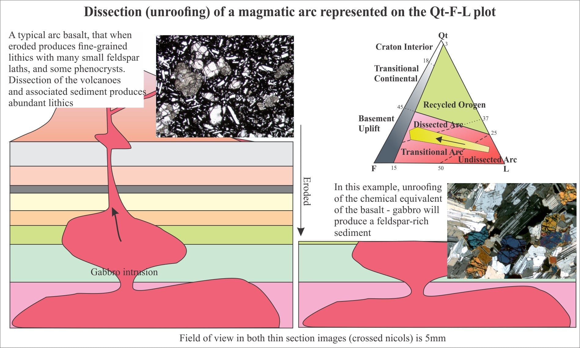
How to… The provenance of sandstones

How to… The mineralogy of sandstones: matrix and cement

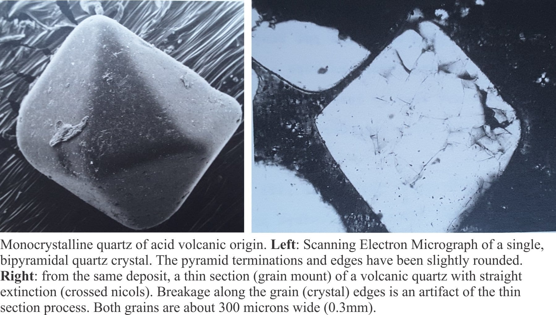
How to…The mineralogy of sandstones: Quartz grains

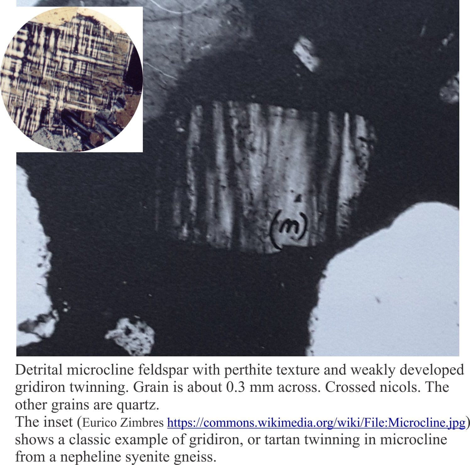
How to…The mineralogy of sandstones: Feldspar grains

How to…The mineralogy of sandstones: lithic fragments

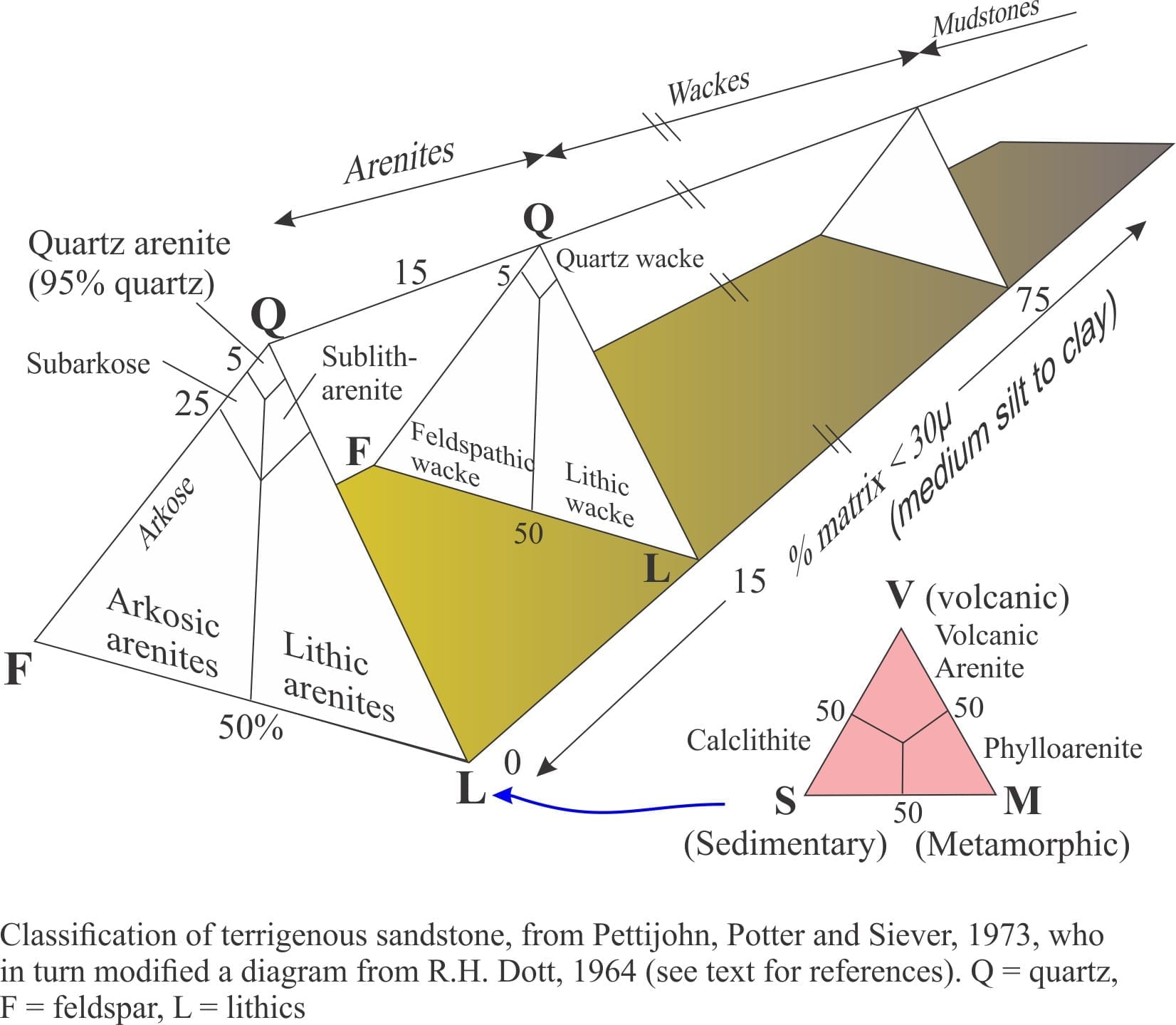
How to… Classification of sandstones

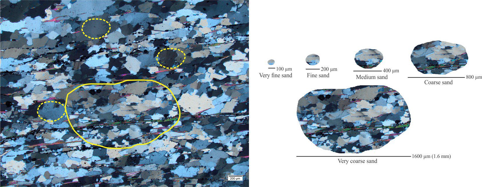
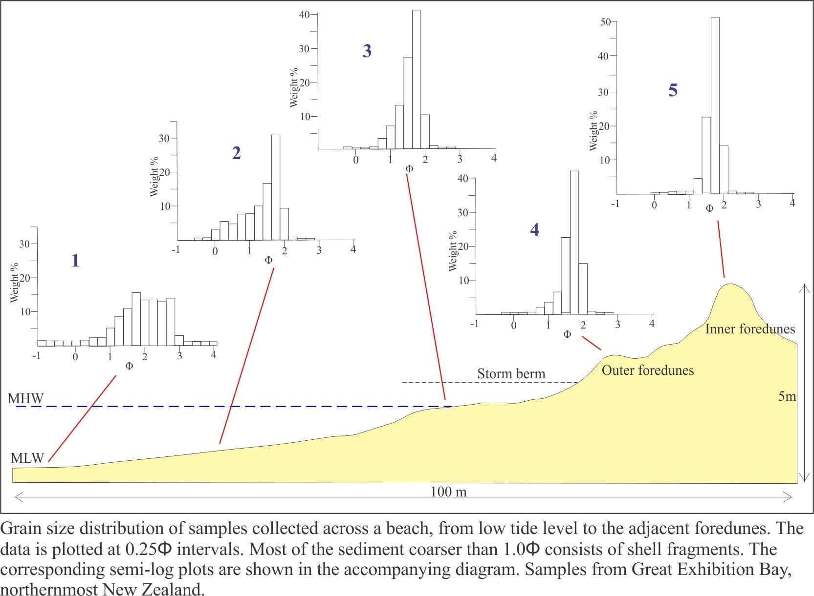
How to… Some controls on grain size distributions

How to… Describing sedimentary rocks – some basics

How to… Grain size of clastic rocks and sediments

How to… Analysis of sediment grain size

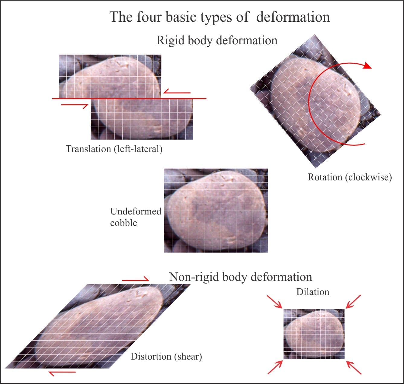
How to… The kinematics of deformed rock

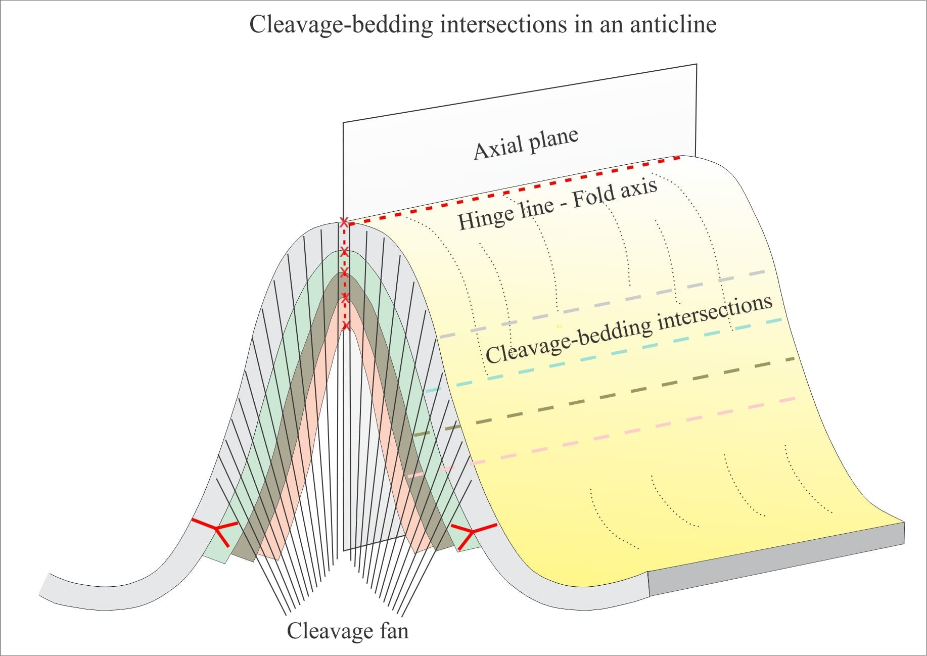
How to…Cleavage and cleavage-bedding intersections 

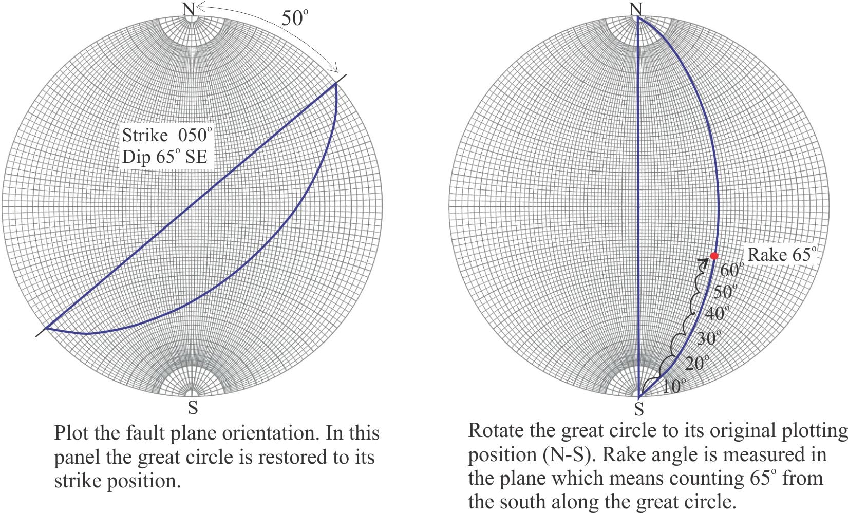
How to… Stereographic projection – poles to planes

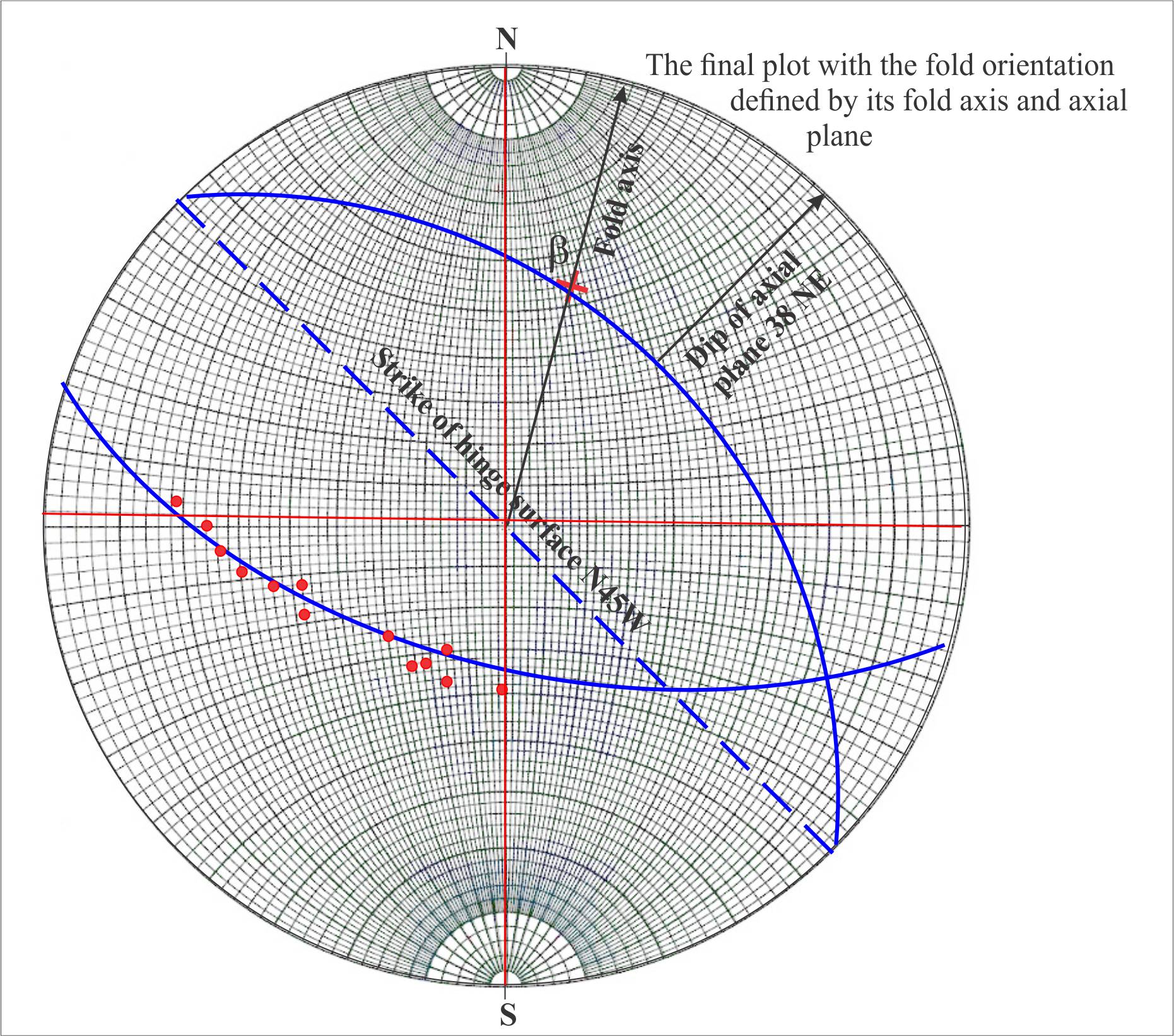
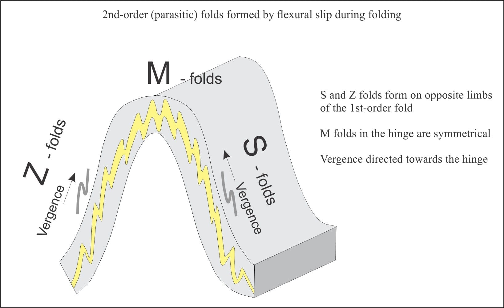
How to… Using S and Z folds to decipher large-scale structures

How to… Folded rock; some terminology

How to… The Rule of Vs in geological mapping

How to… Measuring a stratigraphic section


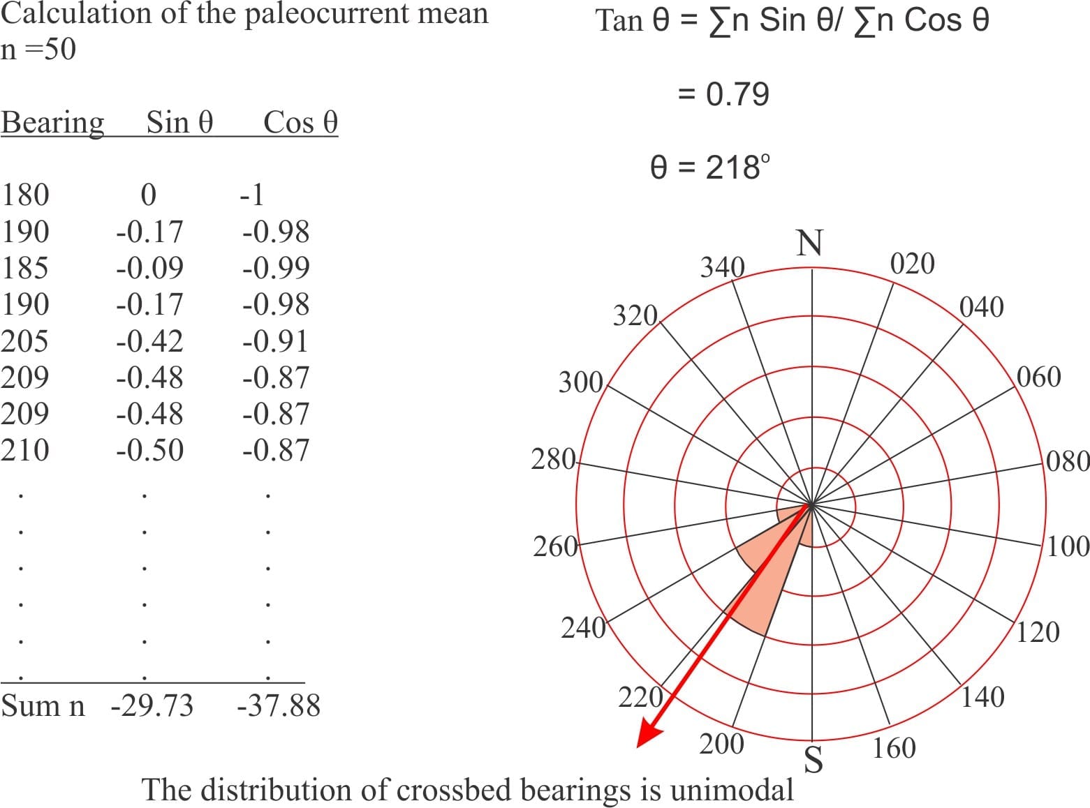
How to … measure and graphically represent paleocurrents.  Three more posts in the How to.. series dealing with stratigraphy and paleocurrents.

How to… Measure dip and strike  A How to… series for field and lab tasks, directed mainly at beginning geology students


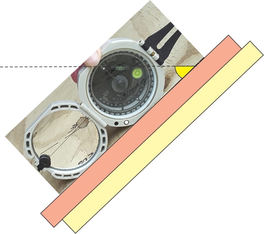
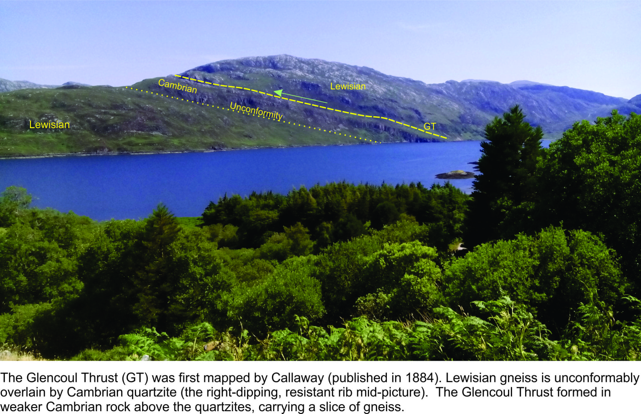
The Moine Thrust:An idea that unravelled mountains


Facebooktwitterlinkedin

3 thoughts on “At home

  1. tom

    Just been reading your post on Fluid Flow: Froude and Reynolds Numbers

    There is a an error in the formula for the Froude number. You have
    F_r = V / \sqrt{g}D
    when it should be
    F_r = V/\sqrt{gD}
    That is, the D should be inside the square root.

    Apart from that, it’s a nice explanation.

    Reply
    1. brian.ricketts@xtra.co.nz Post author

      Yes you are correct. The problem with WordPress symbols is that they are not editable, so the sq root looks like it applies to the g only. Thanks. I’ll add the parentheses.

      Reply

Leave a Reply