Solving the three-point problem

A graphical method for solving the three-point problem

This post is part of the How To… series

Determining the orientation of a plane given the points for three intersecting wells.

Mapping is the essence of geology. Geology maps provide the wherewithal to decipher the time and space organization of Earth’s solid and fluid spheres. We map the outer veneer by directly observing rocks and fluids, ‘walking out’ rock units, measuring, sampling and imaging as we go. More recent tools include all manner of remotely sensed data and satellite imagery (seismic, Lidar, radar, Landsat). We apply the same tools to map other planetary surfaces, although the walking-out is done by remotely controlled rovers.

Subsurface mapping is the essence of all explorations for aquifers, hydrocarbons, minerals, geothermal energy and geotechnical constructions. Subsurface mapping provides us with a deeper (sic) understanding of how the Earth works. Subsurface mapping is entirely dependent on remote sensing (e.g. seismic, gravity, radar) and borehole probing.

The orientation of geological planes in the subsurface is no less important than in surface mapping, but the database is commonly one-dimensional (e.g. borehole depths and lithologies). For example, a zone of mineralization at depth lies beneath an unconformity; knowing the orientation of the unconformity plane will give us more confidence predicting the trend of mineralization (assuming the unconformity is reasonably flat). To solve the problem, we need depths from three borehole intersections with the plane. The solution is commonly referred to as the 3-point problem. It is based on an understanding of dip and strike.

Geometric calculation of dip and strike in a 3-point problem

A graphical solution is shown in the animation. You need paper, a ruler and a protractor. This method requires the horizontal and vertical (depth or elevation) scales to be the same (no vertical exaggeration). Normally the construction would be done on the plane itself (i.e. 2-dimensional) – here the 3-dimensional view has been added to help you visualize the problem.

The animation was made from still images: use the pause and play buttons as you work through the exercise.

Some other useful posts in this series:

Measuring dip and strike

Stereographic projection – the basics

Stereographic projection – unfolding folds
The Rule of Vs in geological mapping

Folded rock; some terminology

Leave a Comment

Your email address will not be published. Required fields are marked *

Archives
Categories
Most Popular
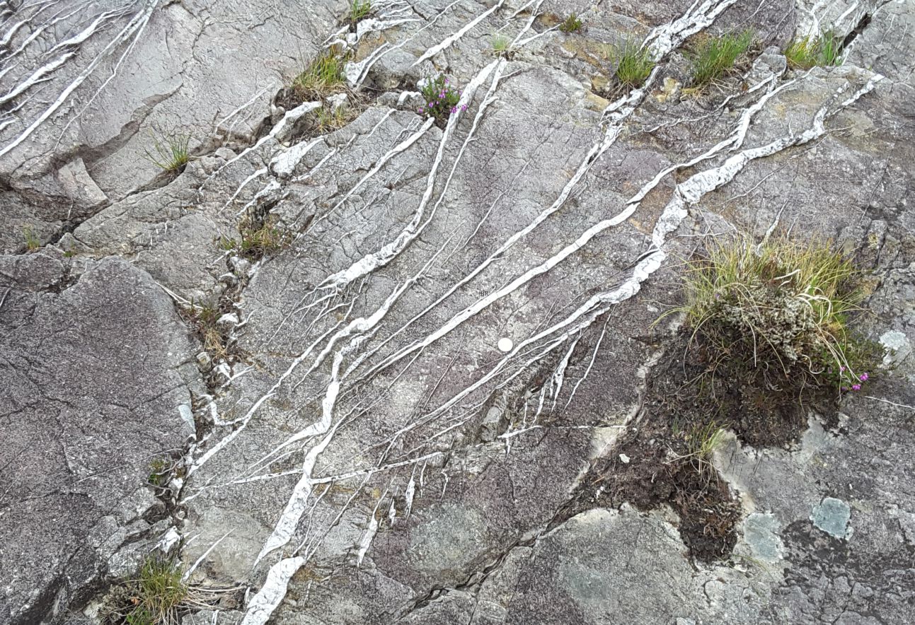
Conjugate fractures and en echelon tension gashes – indicators of brittle failure in Old Red Sandstone, Gougane Barra, County Cork, Ireland.
Mohr-Coulomb failure criteria
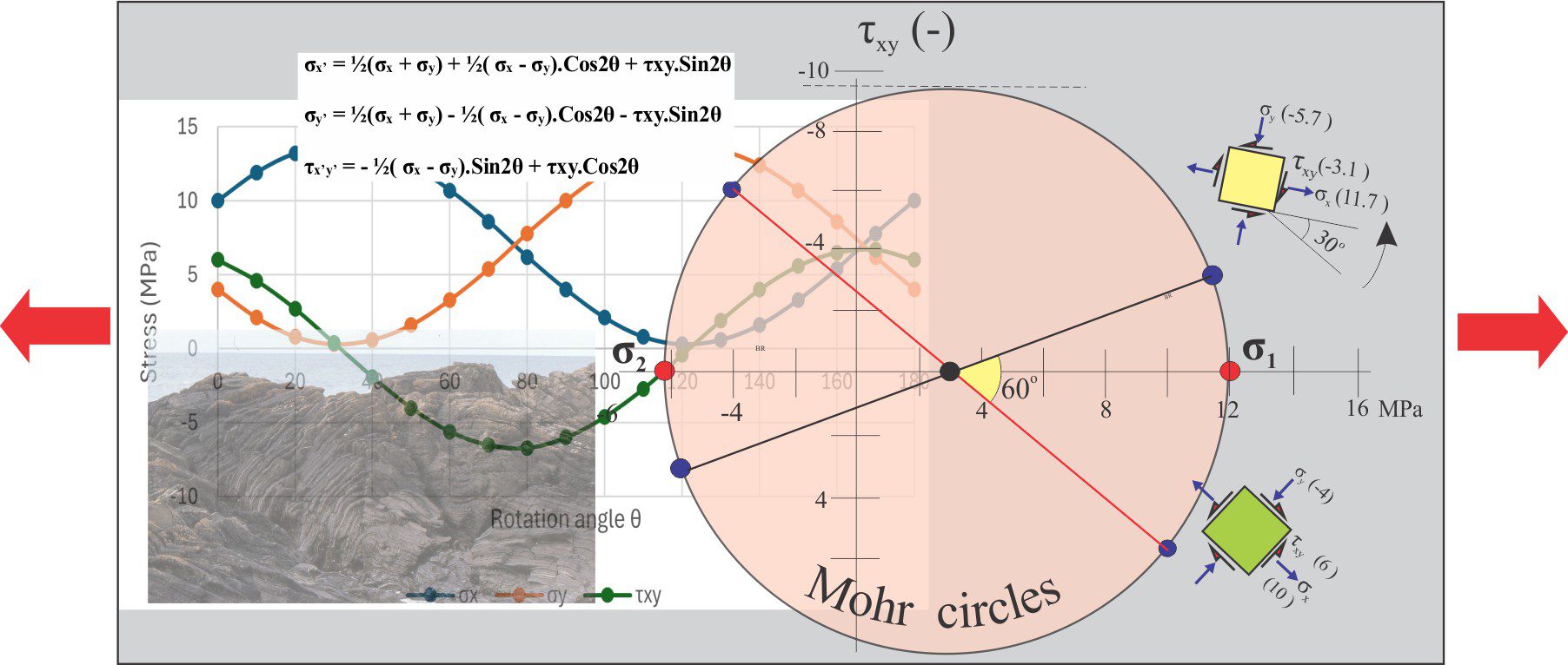
A montage of stress transformation paraphernalia and rock deformation
Mohr circles and stress transformation
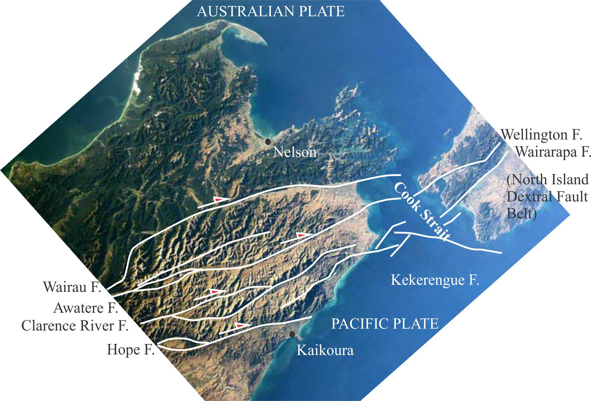
The Marlborough strike-slip fault array extends north from the dextral Alpine Fault transform; faults continue across Cook Strait to join the North Island Dextral Fault Belt in the Wellington region (central Aotearoa New Zealand). In Marlborough and beneath Cook Strait there are several pull-apart basins formed at releasing bend stepovers. Sandbox analogue models can help us decipher the mechanical and kinematic processes that produce structures like these. Base image from NASA – International Space Station 2003.
Strike-slip analogue models
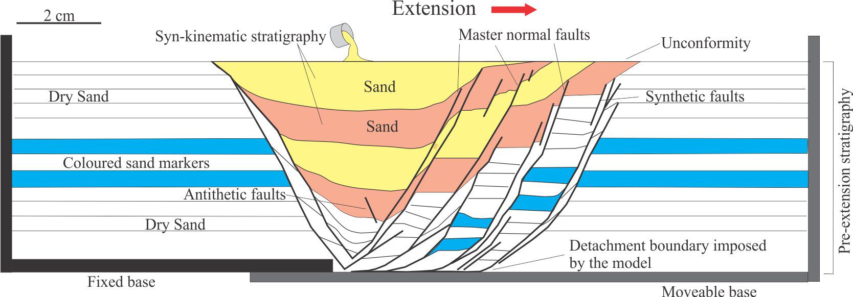
Scaled sand-box experiments are an ideal medium to observe rock deformation that, in this example, involves synkinematic deposition during rift-like crustal extension. The choice of model materials, in addition to imposed boundary conditions such as strain rates, will determine the outcome of the experiment. Dry sand was chosen for this model because its brittle behaviour under the model conditions is a good representation of natural rock failure. Diagram modified slightly from Eisenstadt and Sims, 2005, Figure 3a.
Analogue structure models: Scaling the materials
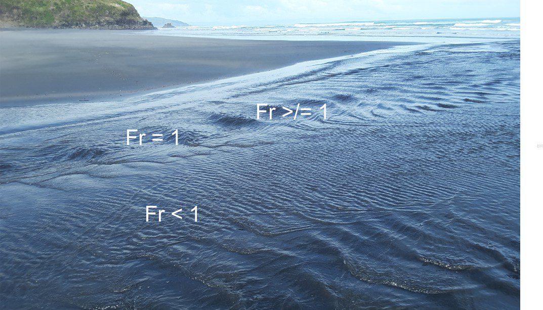
The relationship between inertial and gravitational forces expressed by the Froude number (Fr) is reflected by the changes in surface flows and the formation-decay of stationary (standing) waves. Fr < 1 reflects subcritical (tranquil) flow; Fr>1 supercritical flow. Although the Froude number can be determined experimentally, it can also be eased out of a dimensional analysis of the relevant hydrodynamic variables.
Model dimensions and dimensional analysis
Recent Posts
Conjugate fractures and en echelon tension gashes – indicators of brittle failure in Old Red Sandstone, Gougane Barra, County Cork, Ireland.
Mohr-Coulomb failure criteria
A montage of stress transformation paraphernalia and rock deformation
Mohr circles and stress transformation
The Marlborough strike-slip fault array extends north from the dextral Alpine Fault transform; faults continue across Cook Strait to join the North Island Dextral Fault Belt in the Wellington region (central Aotearoa New Zealand). In Marlborough and beneath Cook Strait there are several pull-apart basins formed at releasing bend stepovers. Sandbox analogue models can help us decipher the mechanical and kinematic processes that produce structures like these. Base image from NASA – International Space Station 2003.
Strike-slip analogue models
Scaled sand-box experiments are an ideal medium to observe rock deformation that, in this example, involves synkinematic deposition during rift-like crustal extension. The choice of model materials, in addition to imposed boundary conditions such as strain rates, will determine the outcome of the experiment. Dry sand was chosen for this model because its brittle behaviour under the model conditions is a good representation of natural rock failure. Diagram modified slightly from Eisenstadt and Sims, 2005, Figure 3a.
Analogue structure models: Scaling the materials
The relationship between inertial and gravitational forces expressed by the Froude number (Fr) is reflected by the changes in surface flows and the formation-decay of stationary (standing) waves. Fr < 1 reflects subcritical (tranquil) flow; Fr>1 supercritical flow. Although the Froude number can be determined experimentally, it can also be eased out of a dimensional analysis of the relevant hydrodynamic variables.
Model dimensions and dimensional analysis
Scroll to Top