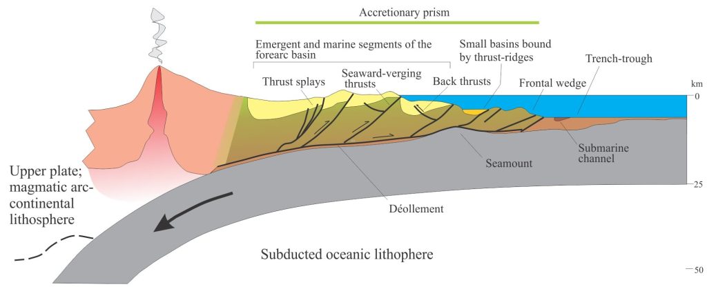

An accretionary prism and forearc basin above a subducting slab of oceanic lithosphere, with a magmatic arc as structural backstop (or buttress) and the main source of sediment.
Forearc basins are kinematically linked to accretionary prisms.
Forearc basins and accretionary prisms are located in the arc-trench gap across accretionary island arc and continent-arc subduction margins. They occupy the upper plate above a descending slab of oceanic lithosphere. As such, they are incredibly dynamic tectono-sedimentary environments; deformation is more or less continuous, driven by large compressive stresses. Sediment sourced from the magmatic arc and related crust is deposited in forearc and trench-slope basins, and in some cases the trench itself. Sediment routing is constantly subjected to modification, in concert with structural changes to sea floor morphology.
The accretionary prism
Accretionary prisms are wedge-shaped stacks of oceanic sediment and some volcanic rock scraped from the top of the subducting lithosphere and plastered over the trench slope. Each slice of sediment is separated by landward-dipping thrusts (i.e. verging towards the trench). Older autochthonous deposits on the upper plate may also be involved in the deformation. Accretion begins at the frontal taper. Landward stacking of thrust panels occurs above a décollement, where the oldest panels are farthest from the trench. The quasi-continuous nature of accretion means that there is jostling along the décollement and the kinematically linked thrust faults through the entire wedge. Like foreland fold-thrust belts, faulting in accretionary prisms is dominated by thrusts, fault splays, back-thrusts and out-of-sequence thrusts. The magnitude of structural shortening across the prism is variable; in some prisms, like that across the Hikurangi margin (New Zealand) a high proportion of shortening is accommodated in the actual subduction zone, rather than in the prism itself (Nicol et al. 2007; Open Access).
Prism width can vary considerably along a convergent margin, from a few kilometres to more than 150 km. Wedges thicken up to 20 km landward from the frontal taper.
Thrust panels consist of older autochthonous rocks plus contemporaneous hemipelagic and pelagic sediment (including radiolarian oozes), turbidites and some volcanics. The occasional seamount also gets caught up in the subduction zone causing blockage and major disruption to the wedge front. The intensity of faulting in accretionary prisms results in much penetrative deformation, manifested as fault breccia, boudinage, cleavage, and generally munched up tectonic melange. Melange can also be derived from slumps, slides, and larger olistostromes, that frequently change the bottom topography on the trench slope.
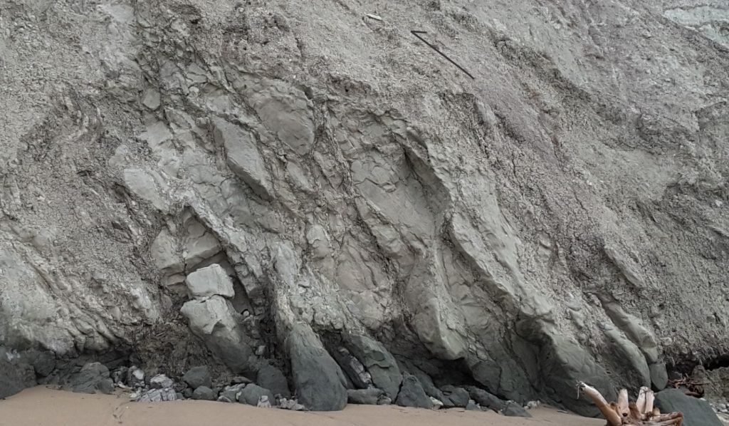

Late Cretaceous to Early Cenozoic sandstone and mudstone, intensely sheared and incorporated into thrust-related melange in coastal exposures of the Hikurangi accretionary prism, Waimarama Beach, New Zealand.
The combination of compressional stress, differential deformation, and low sediment permeability results in elevated fluid pore-pressures during compaction and faulting. Elevated pore pressures reduce the mechanical (shear) strength of rock and sediment, and thus are partly responsible for the intensity of deformation, particularly in newly accreted thrust slices. Some of this fluid escapes to the sea floor, focused by fault and fracture permeability. Sites of sea floor seepage are identified by their unique cold-water seep faunas, carbonate mounds, and acoustic flares from escaping gas, such as methane (e.g. Barnes et al, 2010).
Accretionary prism growth may also take place by subcretion in the zone between the wedge and the subducting slab. In this case, thrust slices are added beneath the wedge as duplex-like structures.
There is significant sediment dispersal across the prism, locally filling small basins bound by thrust fault ridges on the trench slope. Sediment routing can change drastically over the life of a prism because of fault-driven changes to sea floor topography. Submarine canyons and gullies also provide pathways for sediment dispersal across the prism, the lower slope and trench. Sediment transport in this setting is dominated by turbidites and debris flows; submarine slumps and slides also play a significant role on steeper slopes, modifying sediment dispersal routes, and potentially creating loci for dispersal via new gullies.
Sedimentation in the trench
Background sedimentation in the trench (or trough) is primarily pelagic and hemipelagic muds and oozes; if this is the only supply then the trench will be underfilled. If sediment bypasses the accretionary prism, the trench may be filled and even overfilled. Much of this terrigenous sediment is deposited as sediment gravity flows, where transport is at a high angle to the strike of the trench. However, trench basins are continually under modification because at some stage all this sediment will end up being subducted or incorporated into the accretionary prism.
Axial flow along the trench is also possible via deep submarine channels that are fed by submarine canyons or gullies. In this situation, the axial dispersal of facies will be at a high angle to sediment derived from the accretionary prism. An example of this is located along the Hikurangi subduction margin, where the Hikurangi Channel hugs the margin for more than 800 km.
Critical taper theory
One of the most important kinematic theories used to explain the dynamics of accretionary prisms, is critical taper theory. Fold-thrust belts and accretionary prisms are wedge-shaped. In foreland fold-thrust systems the wedge tapers towards the foreland, with the ‘push’ directed from the hinterland, and where the backstop (that has a buttressing effect) is the craton. In oceanic accretionary prisms, the wedge tapers towards the subducting slab; the rigid backstop is the magmatic arc or some other crustal-scale tectonostratigraphic domain, but in this case the pushing forces are directed towards the prism (and countered by the backstop).
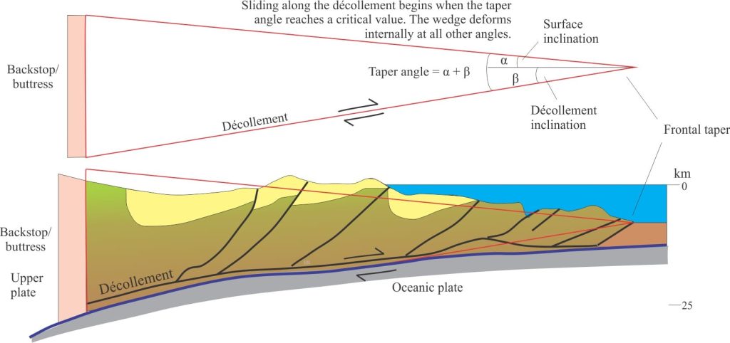

Approximation of an accretionary prism as a wedge, tapered at the subduction-trench boundary. The upper boundary is the prism surface; the lower is the basal décollement. Shear along the décollement will take place when the taper reaches a critical angle.
The analogy of a bulldozer pushing against a pile of snow or sediment illustrates this concept (Davis, Suppe, Dahlem, 1983). As the bulldozer moves forward (applying horizontal compressive stress), the material accumulates in front of the blade initially as a wedge – at a certain wedge slope the entire mass will begin to slide. Critical taper theory posits that the slope, and therefore the angle of the front taper reaches a critical point depending on the strength of the materials (that may be affected by elevated fluid pressures), the cohesion or frictional forces along the décollement, and the slope of that surface. As the critical slope or taper angle is approached, the materials within the wedge will deform – once the critical taper is reached, the entire mass slides along the décollement and there is little subsequent internal deformation of materials other than some minor accommodation along earlier-formed faults (Chappel, 1978).
In accretionary prisms, the wedge taper is constantly adjusting to new slices of ocean sediment being structurally added to the front of the wedge, and to sediment deposited across the top of the wedge. This adjustment promotes deformation of the prism along existing thrusts, including the development of out-of-sequence thrusts.
Forearc basins
Forearc basins are located between the trench slope and magmatic arc or structural backstop. They tend to overlie older segments of the accretionary prism, with the seaward margin onlapping an elevated slope ridge that is cored by a thrust fault or fault splays. As such, forearc basins are part of accretionary prisms, and are subjected to the kind of deformation that effects the entire prism. Thus, forearc basins may be segmented by active, syndepositional faults, leading to the kind of structural telescoping that characterizes the prism.
Forearc basins are a focus for sediment accumulation, and as such will affect the wedge slope and its taper. Thus, deposition in forearc basins plays an important role in the maintenance of the critical taper (Noda, 2018).
Forearc basin strata are expected to contain the full compliment of depositional systems where they onlap arc or continental rocks: fluvial, coastal, shelf, and deeper water submarine fans. Where active volcanic arcs persist, much of the sediment will contain igneous signatures. In situations where there is no active arc, almost any lithological association is possible. For example, Hikurangi subduction margin that defines the plate boundary along northeastern New Zealand, contains an active accretionary prism overlain by a forearc basin, part of which is emergent. The forearc basin contains thick, Pliocene, cool-water limestones that accumulated on shallow shelves washed by tidal currents. Most of these limestones and associated facies are deformed by thrust faults and high-angle reverse faults associated with Pleistocene to Recent deformation in the accretionary prism (Pettinga, 1982; PDF available).
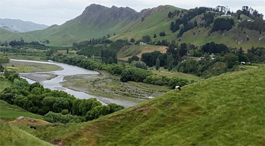

Te Mata Peak sits atop a prominent dip-slope of Pliocene Awapapa Limestone. It is the eroded remnant of a fault anticline that propagated along the tip of a high-angle reverse fault. The limestone is about 3.5Ma; the deformation was mostly post 2Ma. Southern Hawkes Bay, New Zealand. Tukituki River in the foreground.
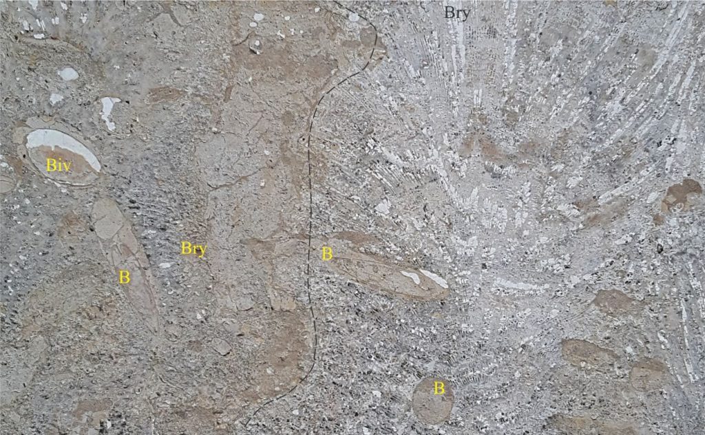

A cut slab of Pliocene limestone from the Hikurangi forearc basin, on the steps of Church Road Winery. Large calcareous bryozoa (Bry – dashed line) have brown mud-filled borings (B). Surrounding sediment contains bivalves (Biv) and abundant mud-filled burrows. Also present are large oysters with Clionid sponge borings, small gastropods and barnacles.
Unroofing sequences have been recognised in some forearc basins. Unroofing represents progressive dissection of a magmatic arc complex, beginning with volcanic edifices and ending with deep intrusive bodies. Erosional unroofing produces a kind of reverse stratigraphy in terms of sediment composition. Thus, older strata in the basin are derived by erosion of lava flows and pyroclastics. As erosion and dissection of the magmatic arc continues these deposits are overlain by sediment derived from deeper intrusions. A classic example of unroofing stratigraphy is found in the Jurassic-Cretaceous Great Valley sequence in California (Ingersoll, 1982, and references therein).
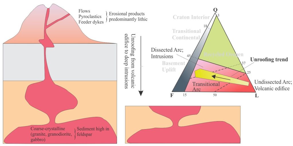

A dissected magmatic arc where erosional unroofing is represented in the ternary plot by changing sandstone compositions (the QFL plot is from Dickinson and Suczek, 1979). Erosion of shallow, mainly effusive volcanics produces lithic-dominated sediment. As the deeper intrusive bodies are exposed, the composition changes to feldspar-dominated. Q = total quartz, F = total feldspar, L = lithics.
Addendum
Here is an excellent addition to the literature on the active Hikurangi subduction margin, eastern New Zealand.
The first of a two volume series of papers on the Hikurangi margin has been published in New Zealand Journal of Geology and Geophysics, Volume 65, Issue 1 (2022). The articles are either Open Access or Free Access. Volume 1 covers topics like: Mass transport deposits, tectonically induced sealevel change, borehole stratigraphy of the slope basin, trench-slope basin fill, deep channel overbank bedforms, seamount volcaniclastics and slow-slip seismics, porosity-permeability of a submarine landslide, stratigraphic signals from a paleolake, and exposed marine terraces on the Wellington coast.
Other posts in this series
Sedimentary basins: Regions of prolonged subsidence
The rheology of the lithosphere
Isostasy: A lithospheric balancing act
The thermal structure of the lithosphere
Classification of sedimentary basins
Stretching the lithosphere: Rift basins
Nascent, conjugate passive margins
Thrust faults: Some common terminology
Basins formed by lithospheric flexure
Basins formed by strike-slip tectonics
Allochthonous terranes – suspect and exotic
Source to sink: Sediment routing systems
Geohistory 1: Accounting for basin subsidence
Geohistory 2: Backstripping tectonic subsidence
Geofluids: Lithosphere-scale fluid flow
Geofluids: Sedimentary basin-scale fluid flow
