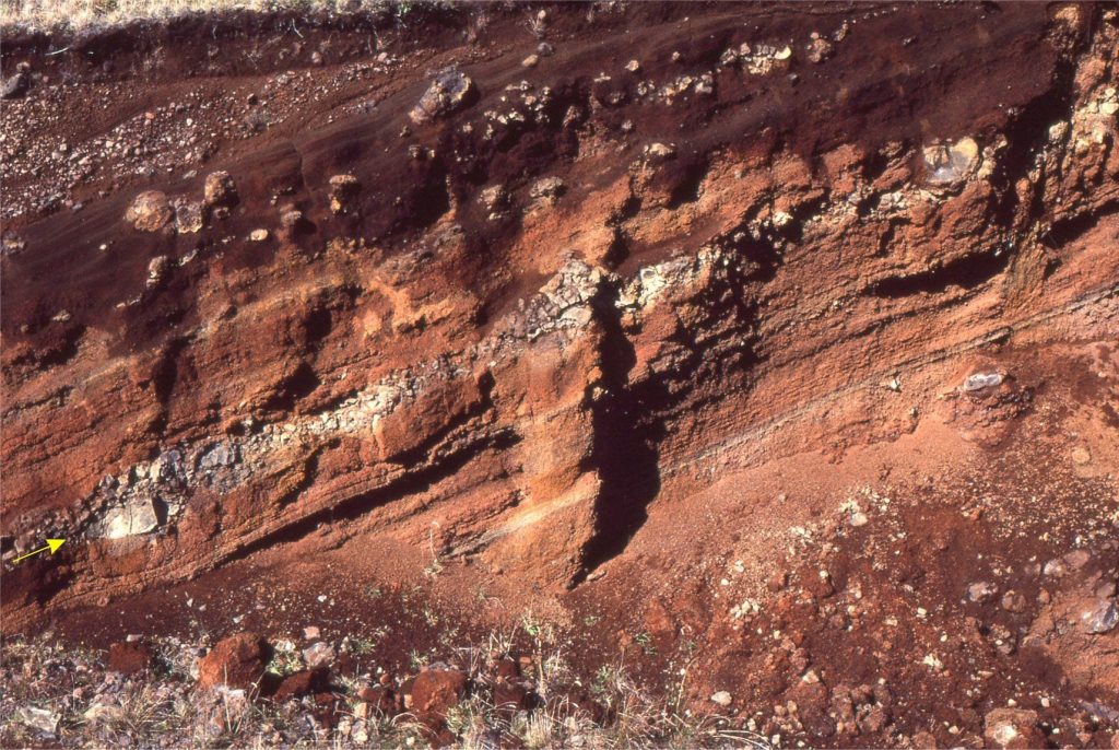
Category Archives: Volcanism

Pyroclastic surges and base surges

Facebooktwitterlinkedininstagram
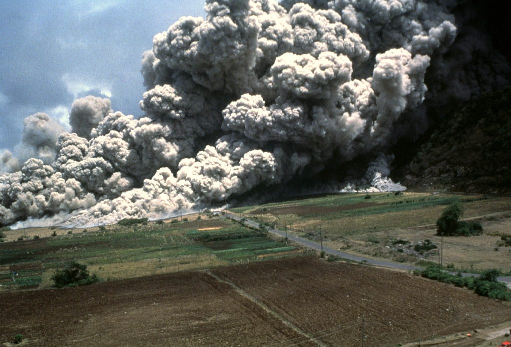
Pyroclastic density currents, including pyroclastic surges, engulf the slopes of Soufrière Hills volcano, Montserrat, during the June 25, 1997eruption. Several people, who apparently did not evacuate the area, were killed; more than 100 houses were destroyed. Image credit: Paul Cole, 1997 (Montserrat Volcano Observatory) and Smithsonian Institution

Pyroclastic density currents, including pyroclastic surges, engulf the slopes of Soufrière Hills volcano, Montserrat, during the June 25, 1997eruption. Several people, who apparently did not evacuate the area, were killed; more than 100 houses were destroyed. Image credit: Paul Cole, 1997 (Montserrat Volcano Observatory) and Smithsonian Institution

Pyroclastic surges, are dilute, ground-hugging turbulent flows of hot, juvenile volcanic particles and a fluid phase of superheated steam and air.


Some historical context

One of the more useful bits of science to come out of the 1940s-50s atmospheric nuclear weapons tests at Bikini Atoll (ie. useful to humanity in general) were observations of surging, ground-hugging flows resulting from shock waves and collapsing particle – water vapour columns. An early description by Young (quoted in Wohletz,1998 – the following historical notes are mostly from his descriptions) notes that the flow “… was a dense toroidal cloud which emerged from the base of the cylindrical column of spray that was formed by the explosion. As the column settled back, it apparently fed material into the base surge, which spread rapidly along the surface of the lagoon”. Initial flow velocities were about 33 m/second (118 km/hr). Flow dynamics within the surge were dominated by turbulence such that its upper boundary mixed with air; the nose of the flow was characterised by “bulges and pockets”. Later ground-based tests revealed thin deposits containing dune-like bedforms. Flow deceleration was primarily a function of gravity, atmospheric drag, and particle dilution through the top of the plume. The term given to these flows was base surge.

Richard V. Fisher was one of the first geologists to observe base-surges derived from nuclear detonation and successfully applied the analogue to ground-hugging flows derived from explosive volcanic eruptions; specifically, the Taal volcano (Luzon, Philippines) and Capelinhos (Faial, Azores) eruptions in 1965 and 1957 respectively (e.g., Fisher and Waters, 1970). Coincidentally, J.G. Moore (1967) observed some dune-like bedforms, like those formed during nuclear tests, in deposits from the Taal event and interpreted them as base surge. He also estimated maximum flow velocities > 50 m/s (180 km/hr), and flow temperatures of 100oC.

Thus, the groundwork for our current understanding of pyroclastic surges was set in motion.


Common traits of pyroclastic surges

Dilute pyroclastic density currents (PDCs), including those referred to as surges or base surges, are turbulent flows of hot, juvenile volcanic particles and a fluid phase consisting mostly of superheated steam and air. Surging PDCs are initiated in several ways (Sulpizio et al., 2014; PDF available):

  • By column collapse of explosive eruptions, particularly hydromagmatic or phreatic maar eruptions.
  • They may decouple from more concentrated PDCs such as ignimbrites, at changes in slope or channel overbank flow.
  • They can also evolve by decoupling from block and ash flows.
  • Initiate directly from magmatic dome collapse.
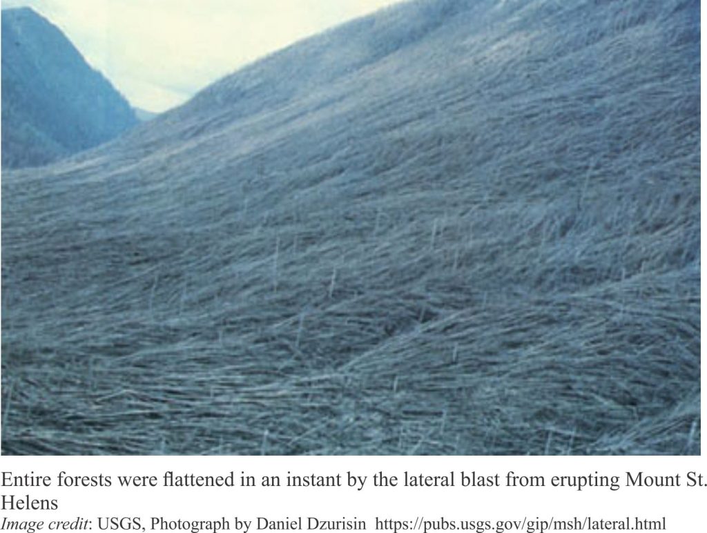
  • From directed, lateral blasts.

Pyroclastic surges have velocities ranging from 10s to several 100 m/s and extend many kilometres from the volcanic vent. Surge deposits tend to be thinner and finer grained than more concentrated PDCs. Stratification is common. The term “bulges-and-pockets” used to describe the nose of detonation-derived base surges has been replaced with the term lobe-and-cleft.


Flow mechanisms

Deposition from pyroclastic surges is fundamentally different to other PDCs. The primary mechanism for flow maintenance in concentrated PDCs is grain-to-grain collisions, although regions of turbulence may develop in the distal or upper parts of flows that have been diluted by elutriation or deposition. In contrast, pyroclastic surges are supported by the turbulent mixing of particles and vapour (Wilson and Houghton, 2000; Pyroclastic transport and deposition); Dufek et al., 2016).  Turbulence begins with flow initiation and is maintained by shear between the top of the flow and overlying plume and air, and shear along the substrate at the base of the flow. An important consequence of this mechanism is that deposition from pyroclastic surges will also be fundamentally different to that derived from concentrated PDCs.

An important paper recently published by Brosch et al., (2021, Open Access) helps elucidate the structure of these turbulent eddies. Their observations of monitored experimental flows combined with direct measurements of the Whakaari eruption in 2019 (White Island, east coast New Zealand) that killed 22 people, enabled them to describe the turbulent structure and pressure variations within pyroclastic surges. Key findings include:

  • Turbulent eddies may be as large as the PDC is deep.
  • Maximum dynamic pressures are carried within the turbulent eddies and surface gravity waves – it is these pressures that maintain momentum and cause physical damage.
  • The turbulent eddies and gravity waves propagate downflow.
  • Propagation of eddies appears to show a degree of periodicity. It is likely that surges at the flow head are linked to these periodic eddies.
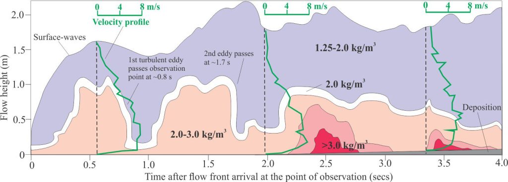
Experimental pyroclastic flow density and flow height profiles, plotted as a function of time since the flow front passed an observation location 3.12 m from the flow initiation point. Density contours have been simplified from Brosch at al., 2021, Figure 3b. Three instantaneous velocity profiles at 550, 1890, and 3350 milliseconds, from their Figure 3a, are superimposed. Sedimentation is indicated by the narrow grey wedge beginning at about 2 seconds. Significant density fluctuations at about 1 and 2 seconds indicate the passage of two turbulent eddies past the observation point. The eddies correspond approximately with the passage of two surface waves. Brosch at al., calculate the periodicity here at about 800 milliseconds. The eddies also correspond to pressure maxima. Maximum velocities occur in the lower half of the flow. The abrupt decrease in velocities at the flow base is probably caused by bed roughness and other frictional losses immediately above the developing traction carpet. Waning velocity and density at 4 s due to sedimentation and elutriation of fine particles to the overlying plume.

Experimental pyroclastic flow density and flow height profiles, plotted as a function of time since the flow front passed an observation location 3.12 m from the flow initiation point. Density contours have been simplified from Brosch at al., 2021, Figure 3b. Three instantaneous velocity profiles at 550, 1890, and 3350 milliseconds, from their Figure 3a, are superimposed. Sedimentation is indicated by the narrow grey wedge beginning at about 2 seconds.
Significant density fluctuations at about 1 and 2 seconds indicate the passage of two turbulent eddies past the observation point. The eddies correspond approximately with the passage of two surface waves. Brosch at al., calculate the periodicity here at about 800 milliseconds. The eddies also correspond to pressure maxima.
Maximum velocities occur in the lower half of the flow. The abrupt decrease in velocities at the flow base is probably caused by bed roughness and other frictional losses immediately above the developing traction carpet. Waning velocity and density at 4 s due to sedimentation and elutriation of fine particles to the overlying plume.

Deposition from pyroclastic surges

Turbulence is partly dependent on the generation of shear along the flow base – shear that arises from bed roughness plus frictional and inertial forces. Flow velocity will be reduced along this shear boundary and at a certain point solid particles will begin to fall from the turbulent suspension forming a traction carpet (e.g., Branney and Kokelaar, 2002). Shear at the traction carpet – flow interface results in stratification, including dune- or ripple-like bedforms. The dunes are three-dimensional constructions – they range in length (measured from crest to crest) from a few centimetres to many metres (analogous to bedforms generated by explosive devices); bedform amplitudes are usually measured in centimetres to 10s of centimetres. Dune crests may be straight and transverse to flow directions, or arcuate analogous to open flow barchan and lunate ripples (Douillet et al., 2013; Open access). Internally, the bedforms contain cross stratification (crossbedding) indicating that they form by accretion of grains transported by a combination of bedload transport, saltation, and fallout from suspension in the overlying flow. The relative contribution of each mechanism may change depending on fluctuating conditions within the flow.

Common bedforms include (Douillet, 2021; open access):

  • Parallel and low-angle stratification.
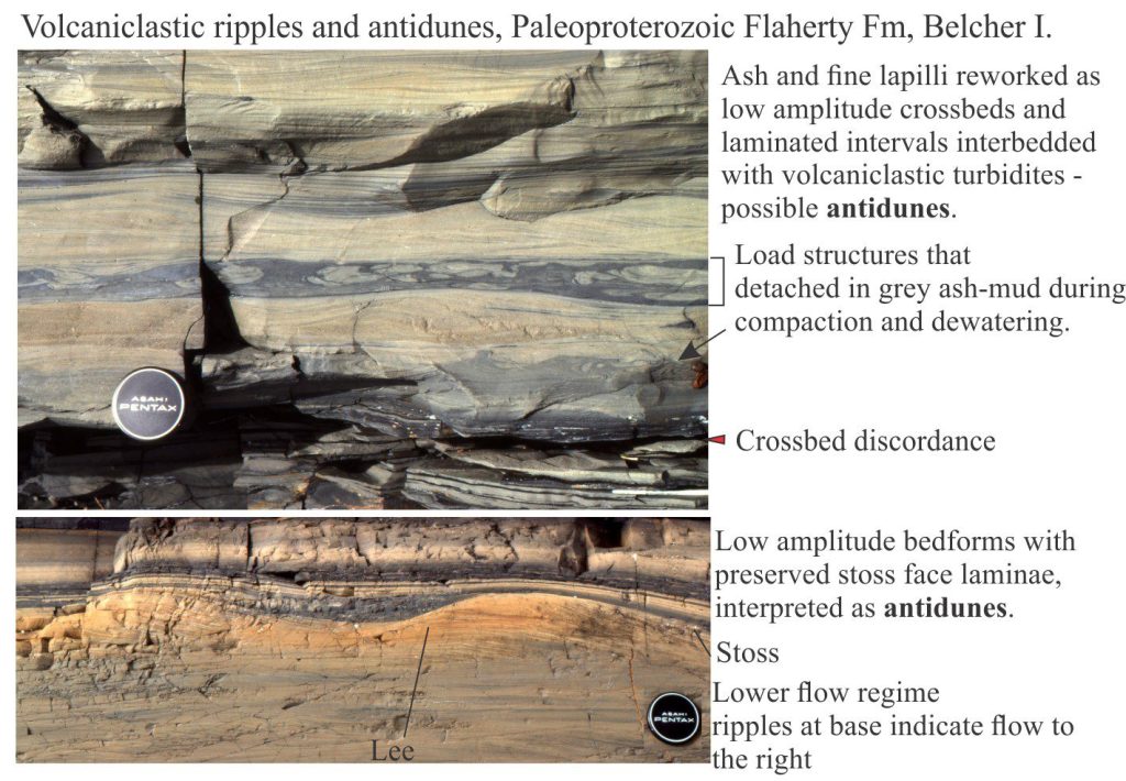
  • Low amplitude ripple- and dune-like bedforms that preserve both lee and stoss slopes. Stoss-side truncations and drapes may also form.
  • Successive ripple or dune trains that climb over the preceding bedforms, in a manner analogous to climbing ripples in some fluvial, tidal, and submarine channels, where deposition is a combination of bedload transport and rapid fallout from suspension.
  • Steep-sided truncation surfaces draped by backset laminae (i.e., laminae that accrete upstream).

A common feature of these bedforms is the preservation of both stoss and lee faces, in contrast to the kinds of bedforms normally associated with fluvial and marine flows where cross stratification is nearly always that which accumulates on lee slopes. The accretion of laminae that gives rise to the surge bedforms may be:

  • Symmetrical (either side of the bedform crest), or
  • Accretion may be dominant in the down-flow direction – these are called progressive laminae that prograde and aggrade down-flow, or
  • Accretion may be dominant in the up-flow direction (regressive laminae); i.e. against the primary current.

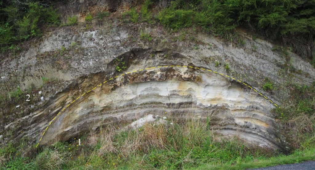
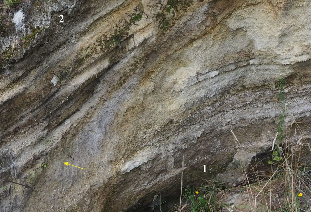
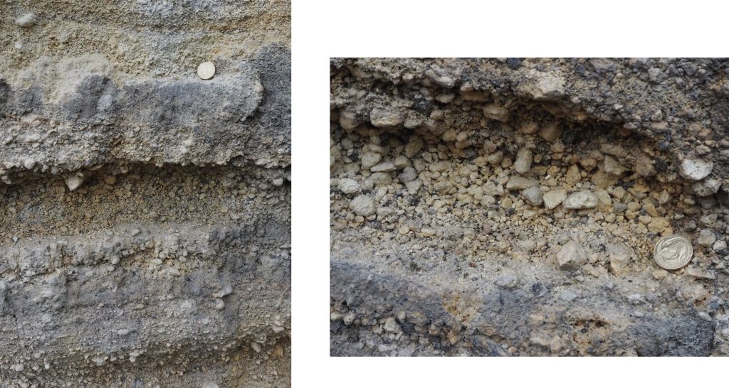
Some of these depositional patterns are shown in the outcrop images below.

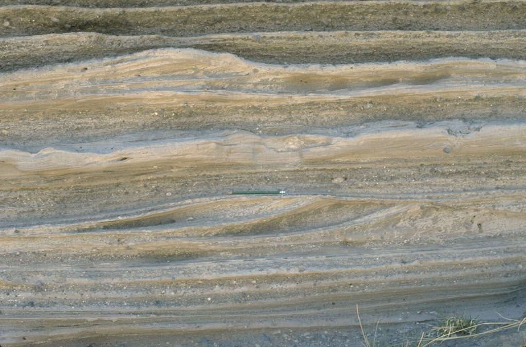
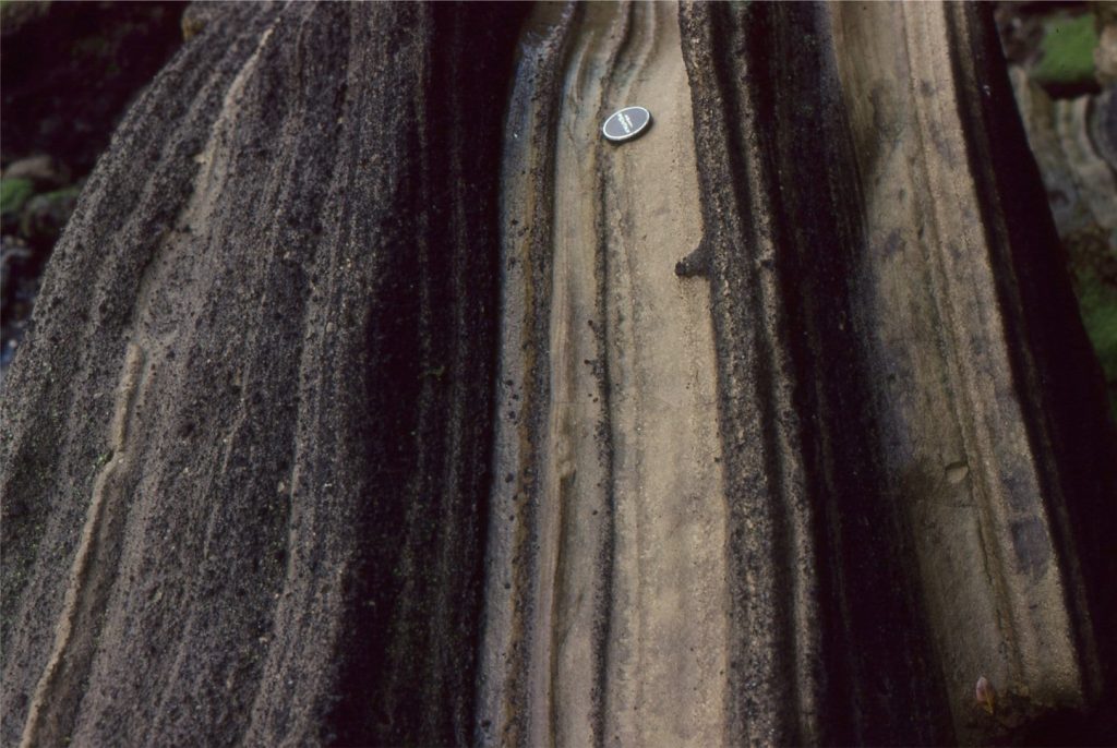
Dunes, truncation surfaces, and stoss-lee slope drape stratification deposited by a pyroclastic surge across Cráter Elegante, during a phreatomagmatic maar eruption about 32 ka (Pinacate volcanic field of NW México). The root structures post-date the surge event. Flow was to the right. Image credit: Bill Rose, 1997 (Michigan Technological University) – Smithsonian Institution

Dunes, truncation surfaces, and stoss-lee slope drape stratification deposited by a pyroclastic surge across Cráter Elegante, during a phreatomagmatic maar eruption about 32 ka (Pinacate volcanic field of NW México). The root structures post-date the surge event. Flow was to the right. Image credit: Bill Rose, 1997 (Michigan Technological University) – Smithsonian Institution


Numerous truncation surfaces (black dotted lines) in this deposit indicate multiple, closely timed and spaced pyroclastic surges. The surge unit at centre-left preserves both stoss and lee slope laminae of a dune that aggraded and prograded down flow (to the right) – the axis of progressive accretion shown by the red dotted line represents the dune crest. The surge deposits are overlain by airfall tephras. The surges originated from lava dome collapse on Mukaijima, part of the Izu-Bonin-Mariana volcanic arc south of Honshu, Japan, that last erupted about 1300 years ago. Image credit: R.V. Fisher, 1979 (University of California Santa Barbara) and Smithsonian Institution.

Numerous truncation surfaces (black dotted lines) in this deposit indicate multiple, closely timed and spaced pyroclastic surges. The surge unit at centre-left preserves both stoss and lee slope laminae of a dune that aggraded and prograded down flow (to the right) – the axis of progressive accretion shown by the red dotted line represents the dune crest. The surge deposits are overlain by airfall tephras. The surges originated from lava dome collapse on Mukaijima, part of the Izu-Bonin-Mariana volcanic arc south of Honshu, Japan, that last erupted about 1300 years ago. Image credit: R.V. Fisher, 1979 (University of California Santa Barbara) and Smithsonian Institution.


Pyroclastic surge deposits with small dune-like bedforms and possible antidunes with backset laminae indicating migration to the left, opposite to the main flow direction. Parallel lamination in the lower part of the section may also reflect upper plane bed conditions. La Breña, Mexico. Image credit: Jim Luhr, 1988, Smithsonian Institution https://volcano.si.edu/gallery/ShowImage.cfm?photo=GVP-03647
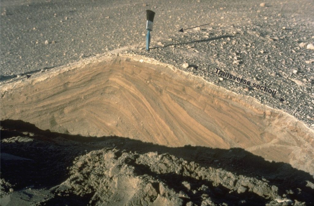
 

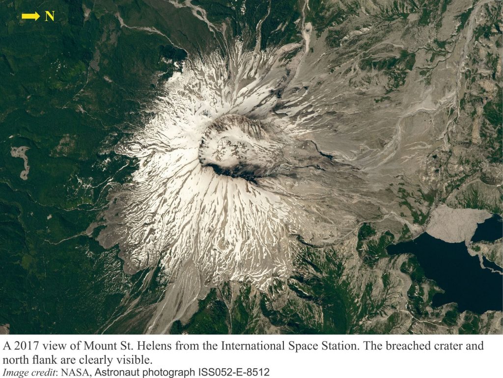
The propagation of multiple turbulent eddies within pyroclastic surges is reflected in this example of a dune from the 1980 Mt. St. Helens eruption, that presents a complex array of cross-strata (note the variable crossbed dips) and truncation surfaces. The excavated sections are transverse and parallel (arrows) to the dune crest. Image credit: Norm Banks, 1980 (U.S. Geological Survey) and Smithsonian Institution

The propagation of multiple turbulent eddies within pyroclastic surges is reflected in this example of a dune from the 1980 Mt. St. Helens eruption, that presents a complex array of cross-strata (note the variable crossbed dips) and truncation surfaces. The excavated sections are transverse and parallel (arrows) to the dune crest. Image credit: Norm Banks, 1980 (U.S. Geological Survey) and Smithsonian Institution


Do these bedforms represent tranquil or supercritical flow?

The terms tranquil (or subcritical), critical and supercritical are used to describe the relationship between surface waves and bedforms in open flow – thanks to William Froude. Open flow in fluvial and marine environments is rarely more than a few metres/s, and usually < 2-3 m/s. At the top end of this velocity range, flow becomes critical where surface waves (also called standing waves) are in phase with bedforms (antidunes) and is supercritical when the surface waves move upstream or break upstream (chutes) – this is also referred to as upper flow regime.  At lower flow speeds (tranquil flow) surface waves move downstream and are out of phase with bedforms (lower flow regime ripples and subaqueous dunes). The preservation of antidunes is rare in normal open flow conditions because the bedforms tend to be washed out during waning flow.

In contrast, pyroclastic surge velocities are 1 to 2 orders of magnitude greater than normal fluvial or marine flows. And although the PDC fluid medium is fundamentally different, critical to supercritical conditions are likely to persist at these velocities. The geometry of the resulting bedforms supports this interpretation:

  • The formation of antidunes commonly involves deposition on both stoss and lee faces that are approximately symmetrical about the bedform crest.
  • Stoss and lee face inclinations are relatively low compared with the angle-of-repose crossbed foresets (lee face) of tranquil flow dunes and ripples.
  • Upstream accretion of bedform laminae on the stoss face will take place if surface waves move upstream during supercritical flow.
  • Steep-sided truncation surfaces may represent erosion during chute and pool conditions (where standing waves break) or even a brief excursion to tranquil flow via a hydraulic jump. Draping of truncation surfaces by stoss and lee face laminae indicate a return to critical or supercritical conditions.

The maintenance of critical – supercritical flow for the duration of these pyroclastic surge events is recorded in the depositional record that contains multiple, vertically stacked, laterally accreting, and truncated bedforms. Each surge event is relatively short lived, (measured in minutes) and deposition is rapid. Bedform preservation potential is high because any excursions to tranquil flow are also short lived.


Related posts

Accretionary aggregates and accretionary lapilli

Block and ash flows

Ignimbrites in outcrop and thin section

Volcanics in outcrop: Pyroclastic density currents

Volcanics in outcrop: Secondary volcaniclastics

Volcanics in outcrop: Lava flows

Volcanics in outcrop: Pyroclastic fall deposits

Fluid flow: Froude and Reynolds numbers

Sediment transport: Bedload and suspension load

The hydraulics of sedimentation: Flow regime

Facebooktwitterlinkedininstagram
Facebooktwitterlinkedin

Accretionary aggregates and accretionary lapilli

Facebooktwitterlinkedininstagram
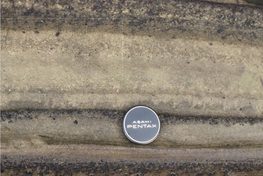
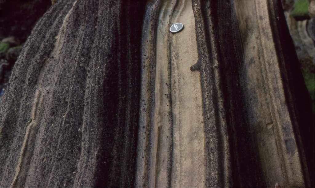
Late Pleistocene airfall ash and lapilli deposits deposited during an explosive (phreatomagmatic) maar eruption (Ihumatao, west Auckland, New Zealand). The darker layers contain greater proportions of basaltic lapilli. The lighter-coloured ash layers (at the lens cap) contain abundant accretionary lapilli.

Late Pleistocene airfall ash and lapilli deposits deposited during an explosive (phreatomagmatic) maar eruption (Ihumatao, west Auckland, New Zealand). The darker layers contain greater proportions of basaltic lapilli. The lighter coloured ash layers (at the lens cap) contain abundant accretionary lapilli.

I have been under the (mistaken) impression that accretionary aggregates, including accretionary lapilli, are occasional odd-ball structures borne of explosive volcanic eruptions. Turns out that, not only are they common in volcanic eruptions that produce ash columns (e.g., plinian, vulcanian eruptions) and plumes atop pyroclastic density currents, but are found in the ejecta of large meteorite impacts (e.g. Sudbury impact structure, Huber and Koeberl, 2017; Open Access). Aggregation of fine ash seems to be the norm and, moreover, is probably an important mechanism for dilution and removal of fine ash from billowing, turbulent ash clouds.

Accretionary aggregates are distinguished from other lapilli by:

  • Their spherical to oblate form, commonly 2-25 mm in diameter.
  • Where present, concentric layers may be continuous or locally discordant.
  • Aggregate cores may consist of ash or a lithic fragment, usually juvenile pumice or more dense fragments of lava.
  • Ash in the aggregate core is commonly coarser grained than that on the rim.

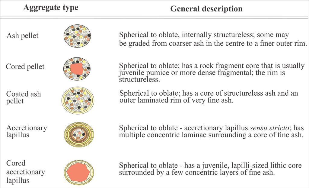
Concentrically layered accretionary lapilli are the most recognizable, but they are part of a spectrum of aggregate forms that includes completely unstructured types. Brown et al., (2010; PDF available) have identified five distinct types based on earlier classification schemes and their own examination of ignimbrite and co-ignimbrite ash deposits on Tenerife, summarized in the diagram below.

The five main types of accretionary aggregate identified by Brown et al (2010). Chart has been redrawn from their Table 1.

The five main types of accretionary aggregate identified by Brown et al (2010). Chart has been redrawn from their Table 1.

How do accretionary aggregates form?

Eruption columns and plumes consist primarily of juvenile fragmental material and a gas phase that consists of water vapour and subordinate CO2 and other volatiles. The volatiles are derived from the original magma, and in some eruptions from groundwater or sea water (particularly phreatomagmatic eruptions). Particles in the eruption column are supported by turbulence, which also means they will be constantly tumbling. Turbulence also acts as an engine that generates electrostatic charges on ash particles – we know this because lightning frequently discharges within eruption clouds. Aggregate accretion is the happy marriage between frequently colliding, electrically charged ash particles and water bonding. Freezing may also occur in columns that penetrate the upper atmosphere.

A useful and more familiar analogue for this process is the formation of hail, or hailstones during thunder storms and tornadoes. The diagram below describes the accretion of supercooled water droplets and small ice crystals to a hailstone as it spins in the updraft of a cumulonimbus cloud. The ice crystals develop positive electrostatic charges in the upper part of the cloud and the growing hailstones negative charges in the lower part of the cloud – hence the electrical discharges. The hailstone analogy seems reasonable given the similar geometric structures of hail and accretionary lapilli, the role of electrostatic charges, and the violent, turbulent movement of particles that sustain both storm clouds and eruption columns.

A possible analogue for volcaniclastic aggregate accretion. The basic science of hail formation is summarized from the National Weather Service. The hail image was cropped from a Wikimedia original.

A possible analogue for volcaniclastic aggregate accretion. The basic science of hail formation is summarized from the National Weather Service. The hail image was cropped from a Wikimedia original.

Like hail, volcaniclastic aggregate size is probably dependent on the amount of time spent tumbling through an eruption cloud. At some point the aggregates will be too heavy to be maintained by the column turbulence and will fall, along with other fragmentals of similar density and size. Their preservation upon sedimentation will depend on how tight the aggregate particles are bound. Indeed, the preservation potential of many aggregates is probably low if the only mechanisms holding them together are static electricity and a film of water. Aggregates that are frozen at high elevations will likely disaggregate as they fall through warmer air. However, many accretionary aggregates, particularly accretionary lapilli (those with concentric layering) are preserved intact, deformed by compaction, or broken (i.e., brittle behaviour) which implies they are significantly more robust, inviting the suggestion that an additional particle bonding process operates during formation.


Experiments on aggregate binding

One possible mechanism involves rapid precipitation (in the eruption cloud) of sulphate and chloride salts, and that these precipitates cement aggregate particles. Experiments to test this hypothesis were conducted by Mueller et al., 2016, using a fluidized bed containing small glass beads and natural volcanic ash. Fluidization was maintained with a flow of hot air. Loosely bound aggregates formed when water vapour was introduced to the air stream but their preservation during sedimentation was low. The number of aggregates formed in this way increased with increasing humidity. Preservation of aggregates was only achieved when NaCl solution was added to the air stream, coating the beads and ash particles. Examination of the aggregates showed that small NaCl crystals had precipitated at particle contacts within the fluidized bed (i.e., prior to deposition) – in effect, acting as cement. Both Na and Cl are common dissolved constituents in aerosols and the water-vapour phase of eruption columns (in addition to other halides and sulphates), lending credence to the experiment results.


Some examples

A well layered accretionary lapillus from Darwin Volcano, Galapagos Islands. Ash in the lapillus core is slightly coarser-grained than that on the rim. This example has about 50% porosity that, upon burial, would either collapse during compaction, or fill with cement. Image credit: David Lynch, 2013.

A well layered accretionary lapillus from Darwin Volcano, Galapagos Islands. Ash in the lapillus core is slightly coarser-grained than that on the rim. This example has about 50% porosity that, upon burial, would either collapse during compaction, or fill with cement. Image credit: David Lynch, 2013.


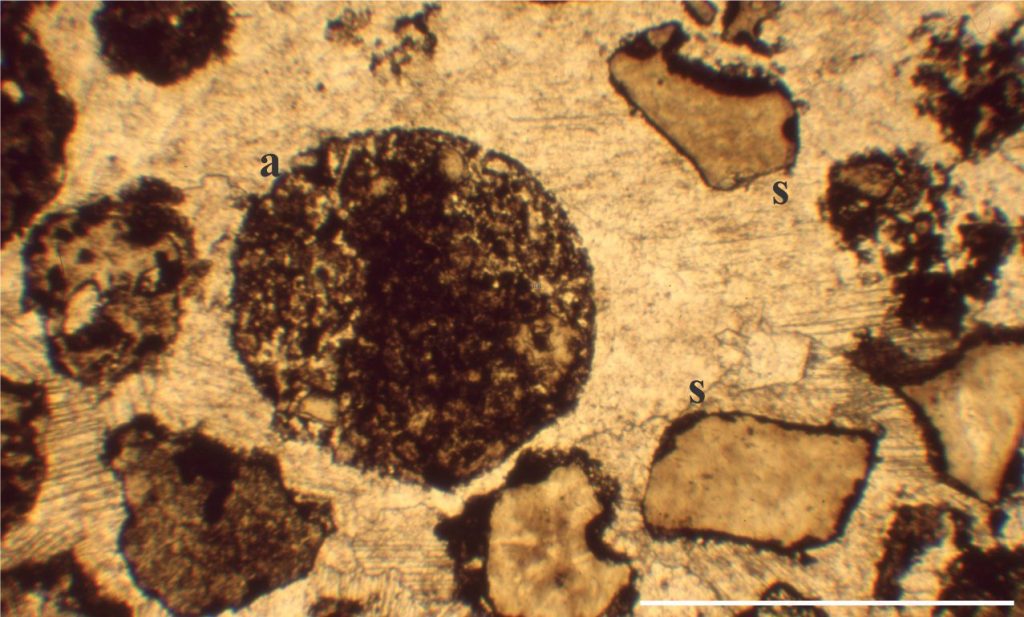
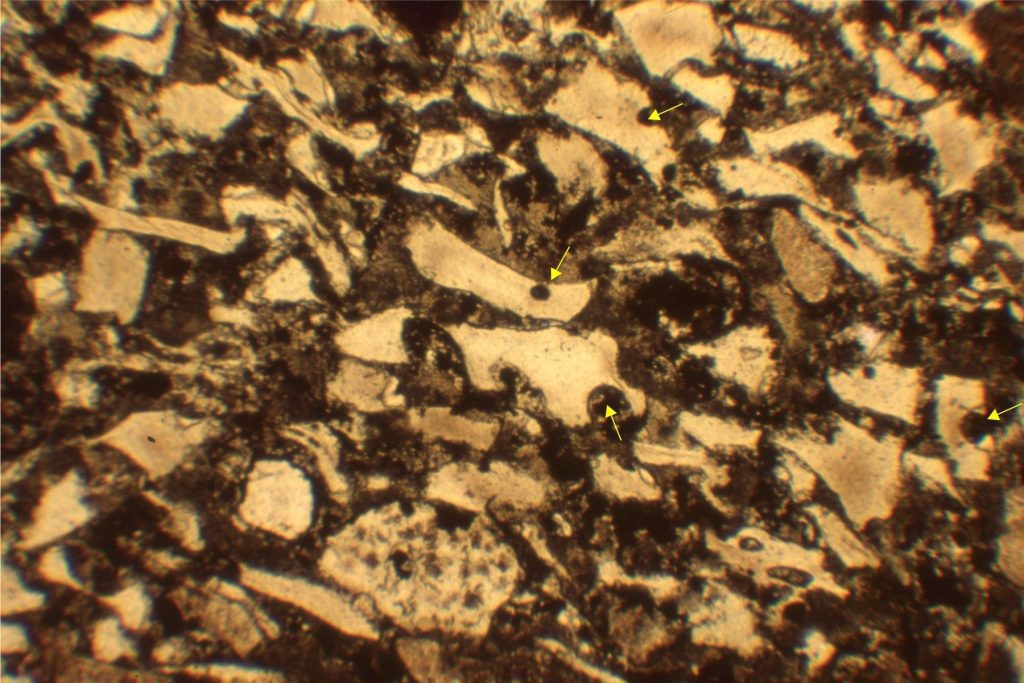
A non-structured accretionary pellet of fine ash (a) within a thick, Paleoproterozoic pyroclastic density current. The aggregate core is more densely packed than the rim. Associated fragmentals include shards (s - glass replaced by silica and some calcite) and pumice fragments. All fragments occur within later diagenetic calcite cement. Bar scale is 4 mm. Flaherty Fm. Belcher Islands.

A non-structured accretionary pellet of fine ash (a) within a thick, Paleoproterozoic pyroclastic density current. The aggregate core is more densely packed than the rim. Associated fragmentals include shards (s – glass replaced by silica and some calcite) and pumice fragments. All fragments occur within later diagenetic calcite cement. Bar scale is 4 mm. Flaherty Fm. Belcher Islands.


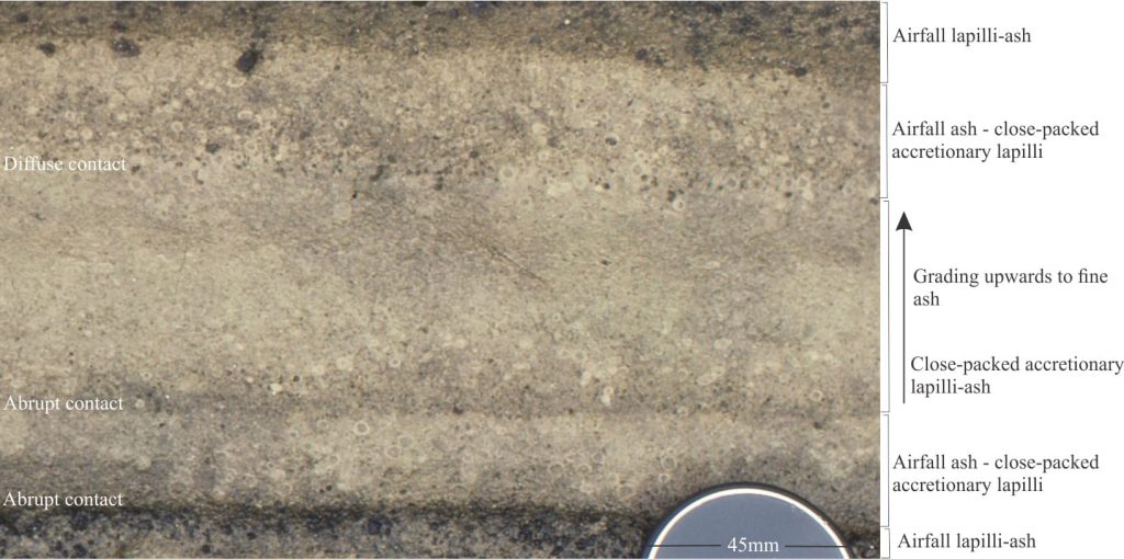
Late Pleistocene airfall layers with accretionary lapilli that have concentrically layered rims and structureless cores. Most aggregates here are symmetrical; a few are elongate parallel to bedding, possibly due to compaction. They range from 3 to 8 mm in diameter. The packing arrangement of the lapilli is clast-supported. Darker tephra layers contain higher proportions of basaltic ash and lapilli. This is the same outcrop shown in the image at top of page. Detail in the inset is shown below. Lens cap is 50 mm diameter.

Late Pleistocene airfall layers with accretionary lapilli that have concentrically layered rims and structureless cores. Most aggregates here are symmetrical; a few are elongate parallel to bedding, possibly due to compaction. They range from 3 to 8 mm in diameter. The packing arrangement of the lapilli is clast-supported. Darker tephra layers contain higher proportions of basaltic ash and lapilli. This is the same outcrop shown in the image at top of page. Detail in the inset is shown below. Lens cap is 50 mm diameter.


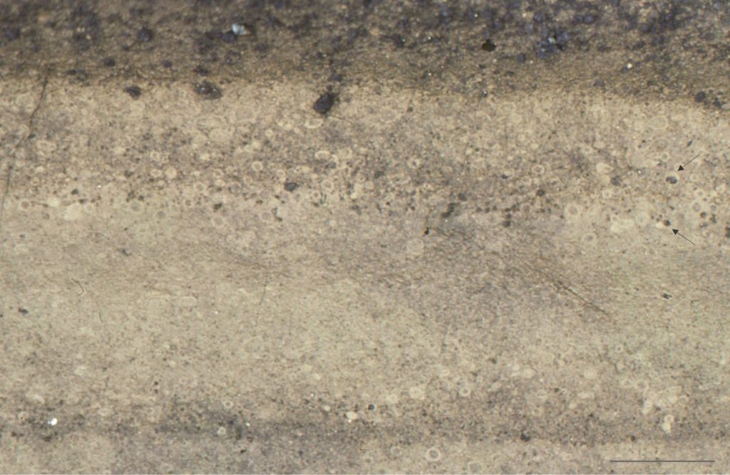
A closer look at the Late Pleistocene accretionary lapilli shown in the previous image. Most lapilli have ash cores and much finer-grained concentric rims. A few have solid, dark basalt cores (arrows). Bar scale is 25 mm long.

A closer look at the Late Pleistocene accretionary lapilli shown in the previous image. Most lapilli have ash cores and much finer-grained concentric rims. A few have solid, dark basalt cores (arrows). Bar scale is 25 mm long.


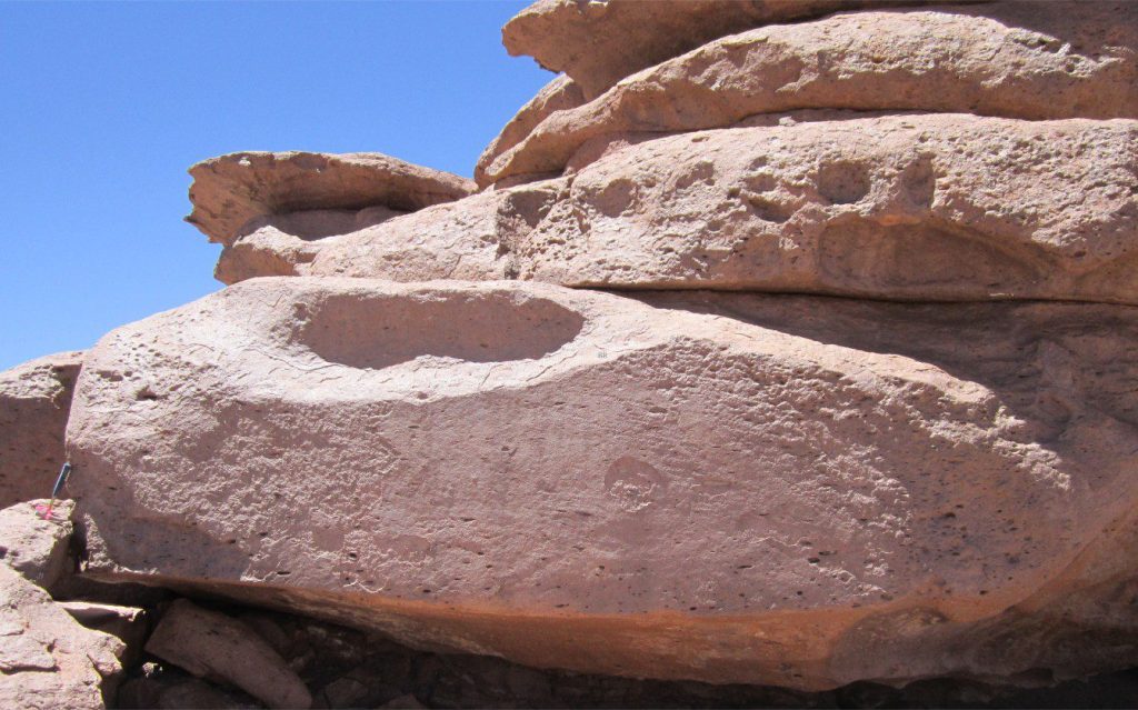
A thick bed of spherical and subspherical accretionary aggregates associated with explosive Miocene andesitic eruptions and rhyo-dacitic ignimbrites, Chilean Altiplano. There is a mix of ash pellets and ash-cored accretionary lapilli. Lapillus diameters range from 8 mm to 25 mm. Lapilli are packed in a clast-supported framework.

A thick bed of spherical and subspherical accretionary aggregates associated with explosive Miocene andesitic eruptions and rhyo-dacitic ignimbrites, Chilean Altiplano. There is a mix of ash pellets and ash-cored accretionary lapilli. Lapillus diameters range from 8 mm to 25 mm. Lapilli are packed in a clast-supported framework.

Coated ash pellets

The two image pairs below show coated ash pellets (aggregates) in the Late Miocene – Pliocene Minden Rhyolite, a stratigraphic unit associated with caldera collapse, rhyolite dome extrusion, and PDCs including partly welded to non-welded ignimbrites and pyroclastic surges. Caldera formation was part of the Miocene-Pliocene Coromandel Volcanic Zone – an older cousin to Taupo Volcanic zone, eastern New Zealand. The northern limit of the caldera structural boundary coincides with Whitianga township. These outcrops are located at the north end of Hahei Beach, eastern Coromandel.

Coated ash pellets in successive airfall ash layers, sandwiched between non-welded ignimbrite, pyroclastic surge deposits, and thick flow-banded rhyolite lava flows or domes. The aggregates stand out because of darker ash in the outer rims. The pellet cores tend to weather negatively, producing a pockmarked outcrop. In the left image, the pellets are are relatively few, mixed with finer, pale coloured ash and crystals. The pellets are more concentrated, locally clast-supported, in the right image.

Coated ash pellets in successive airfall ash layers, sandwiched between non-welded ignimbrite, pyroclastic surge deposits, and thick flow-banded rhyolite lava flows or domes. The aggregates stand out because of darker ash in the outer rims. The pellet cores tend to weather negatively, producing a pockmarked outcrop. In the left image, the pellets are are relatively few, mixed with finer, pale coloured ash and crystals. The pellets are more concentrated, locally clast-supported, in the right image.


Detailed views of the coated ash pellets shown above, from the Minden Rhyolite. The accretionary coatings occur as single and sometimes up to three layers (black arrow, right image). Ash in the aggregate cores is almost indistinguishable from the ash in the host sediment. The aggregate cores are softer than the rims - they weather negatively, possibly because of early cementation of the rims in the eruption column. Red arrows (left image) point to feldspar crystals.

Detailed views of the coated ash pellets shown above, from the Minden Rhyolite. The accretionary coatings occur as single and sometimes up to three layers (black arrow, right image). Most pellets are spheroidal to subspheroidal; a few are elongated, possibly from indentation by neighbouring pellets. Ash in the aggregate cores is almost indistinguishable from the ash in the host sediment. The aggregate cores are softer than the rims – they weather negatively, possibly because of early cementation of the rims in the eruption column. Red arrows (left image) point to feldspar crystals.

Related posts

Block and ash flows

Ignimbrites in outcrop and thin section

Volcanics in outcrop: Pyroclastic density currents

Volcanics in outcrop: Secondary volcaniclastics

Volcanics in outcrop: Lava flows

Volcanics in outcrop: Pyroclastic fall deposits

Facebooktwitterlinkedininstagram
Facebooktwitterlinkedin

Block and ash flows

Facebooktwitterlinkedininstagram
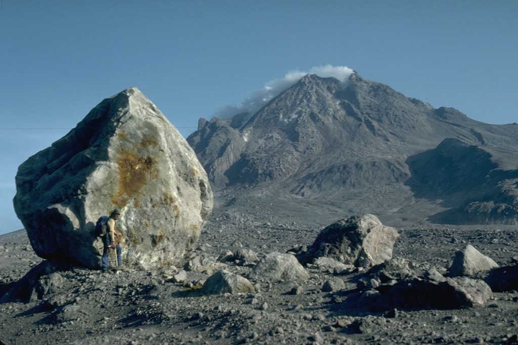
This 6 m high lava block was carried 4 km down the flank of Augustine volcano (Alaska) by a block and ash flow during the 1976 eruption. Image Credit: Harry Glicken, 1986 (U.S. Geological Survey/Smithsonian Inst.)

This 6 m high lava block was carried 4 km down the flank of Augustine volcano (Alaska) by a block and ash flow during the 1976 eruption. Image Credit: Harry Glicken, 1986 (U.S. Geological Survey/Smithsonian Inst.)

Block and ash flows – a hot pyroclastic flows that transport big chunks of rock


Block and ash flows (BAFs) are distinguished from other pyroclastic density currents (PDC) by their coarse blocky textures and derivation from the collapse of lava domes. Like any PDC, they are fast moving, hot, and capable of wrecking widespread death and destruction. Well known historical examples of eruptions that produced devastating PDCs following lava dome collapse include Soufriere (1902, 1979), Mount St. Helens (1981), Merapi (Indonesia,2006), and Unzen (Japan, 1990-95).

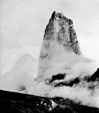
The Mt Pelée spine began growing October 8, 1902, about 4 months after the catastrophic nuée ardent that destroyed the town of Saint-Pierre. Growing up to 15 m per day, it reached a height of 300 m. Collapse of this spine also generated block and ash flows. Image credit: Angelo Heilprin, 1902, one of the first geologists on the scene after the eruption.

The Mt Pelée spine began growing October 8, 1902, about 4 months after the catastrophic nuée ardent that destroyed the town of Saint-Pierre. Growing up to 15 m per day, it reached a height of 300 m. Collapse of this spine also generated block and ash flows. Image credit: Angelo Heilprin, 1902, one of the first geologists on the scene after the eruption.

Diagnostic field and outcrop characteristics derived from observations of recent PDCs and ancient deposits include:

  • Like most PDCs, a BAF consists of a lower, concentrated blocky ash flow overlain by a more dilute, billowing (turbulent), surging ash plume that deposits finer grained, commonly stratified ash and lapilli.
  • Flow speeds up to 30 m/sec are common (~100 km/hr); slower than ignimbrites, but still difficult to outrun!
  •  Fragments are usually dense, poorly vesicular lava, rather than the highly vesicular pumices characteristic of ignimbrites.
  •  Fragments commonly show flow banding and vesicle alignment inherited from the parent lava dome.
  •  Compositions range from andesite to rhyolite (the compositions of the parent lava domes), tending towards the more felsic end of that spectrum.
  •  They are hot (up to 600o C) but tend to be non-welded. Entrained vegetation is incinerated or carbonised.
  •  Their distribution is governed primarily by topography, thickest in valleys (10s of m thick), but potentially spilling over adjacent interfluves. Most recent BAFs have runout distances of a few kilometres down the flanks of the volcanic edifice from which they originated (e.g., Merapi, Unzen). One notable exception has been observed in recent flows on Shiveluch volcano (2005, 2010, Kamchatka) where blocks 5 m in diameter were transported 15 km from the lava dome ( Krippner et al., Characterizing the 2005 and 2010 giant block-and-ash flow deposits at Shiveluch using high-resolution satellite and field data. In press, Volcanica).
  •  They are poorly sorted, and either non-graded or show some degree of normal or reverse coarse-tail grading.
  •  Closely spaced stratigraphic sections may show significant variability in thickness, grain size distribution and grading, and stratification.
  •  BAFs are commonly associated with pyroclastic surges.
  •  BAFs are likely to be interstratified with airfall deposits and large ballistics derived from explosive eruptions, other PDCs derived from collapsing plinian and vulcanian eruption columns, and lahars deposited in intervals between eruptive episodes. 

    Lava domes

    Block and ash flows are mostly derived from the collapse of lava domes. Compared to PDCs, the growth of lava domes is a relatively quiet affair, in craters or adjacent flanks of volcanoes at the outlet of active vents. They tend to form from viscous lava at the felsic end of the compositional spectrum, although variations in viscosity will determine the manner in which magma is extruded. Two basic styles of extrusion and dome growth are recognized:

    BAF deposits consist of angular to subrounded juvenile fragments ranging from lapilli to blocks exceeding 10 m across, set in a finer ash matrix. The proportion of matrix is variable – those BAFs with minimal matrix are referred to as fines-poor or fines-depleted.

    1. Endogenic domes that expand as magma is intruded into the dome interior (i.e., they inflate from within), and
    2. Exogenic domes that grow externally by addition and stacking of lava flows.

There are variations between these two end-members and one style of extrusion may evolve into the other depending on changes in magma composition, viscosity, and extrusion rate (Fink and Anderson, 2000). Dome shapes range from symmetrical, hemispherical structures, to steep-sided spines. Growth of lava domes is accompanied by development of flow banding, shear zones, and fractures indicating that flow rheology can involve both ductile and brittle behaviour. The outer carapace of cooled lava is characteristically fractured during cooling and dome expansion (extensional fractures), leading to an almost continuous supply of angular fragments accumulating in talus fans around the dome base (these are mostly cold deposits). Talus debris can be incorporated into PDCs or redeposited as lahars.

The Mount St. Helen dome in, 1984 (left) continued to grow until 1986 – at this point it was 1.1 km wide and 250 m high. Image credit: Lyn Topinka, 1984 (U.S. Geological Survey/Smithsonian Inst.).

The Mount St. Helen dome in, 1984 (left) continued to grow until 1986 – at this point it was 1.1 km wide and 250 m high. Image credit: Lyn Topinka, 1984 (U.S. Geological Survey/Smithsonian Inst.). Right: Mount St. Helen 2005 spire-like extrusion where fracturing and spalling provide debris for talus aprons. Image credit: U.S. Geological Survey, Cascades Volcano Observatory/Smithsonian Inst.).

Lava domes are inherently unstable. Dome collapse is driven by gravity acting on fractured, oversteepened slopes, or explosively from internal pressures. Gravitational slope failure may also lead to explosive behaviour – the major eruption at Mount St. Helens in 1981 was caused by the concatenation of such processes – a bit like popping the cork from a bottle of soda water (or champagne). Dome collapse is caused by (Ashwell et al. 2018):

  • Gravitational instability of oversteepened, fractured dome surfaces.
  • Undercutting of the dome base by slumping.
  • Oversteepening caused by rapid increases in extrusion producing inflation or bulging.
  • High precipitation.

Collapse of an actively growing dome will release hot rock and volatiles – it is these materials that produce the pyroclastic density currents – primarily block and ash flows and pyroclastic surges.


BAF flow mechanisms

BAFs are generally considered to act as concentrated flows of blocks and finer ash. However, unlike cold (non-volcanogenic) debris flows there is probably minimal matrix strength to support the flow. Instead, BAFs are often compared with grain flows where flow is maintained by dispersive pressures. This mechanism was first discovered by R.A. Bagnold from a combination of theory and experiments with moving sediment – fluid mixtures. Dispersive pressures derive from interparticle collisions in a fluid, and these collisions transfer momentum from one fragment to another, but in the process lose some kinetic energy. Reverse (or inverse) grading is a common manifestation of this process in grain flows and some debris flows, including lahars; this is the case where large fragments move to the top of the flow because they experience greater dispersive pressures than smaller fragments. Some BAFs also exhibit normal grain size grading or normal coarse-tail grading which suggests deposition from a waning turbulent flow. Thus, it is possible that BAFs, like other kinds of sediment density currents, undergo flow transitions as the flow evolves.

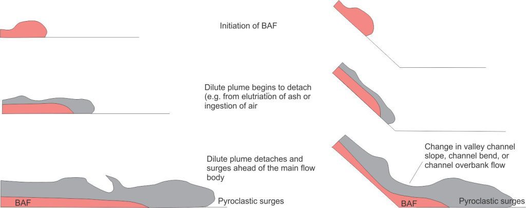
Observations of recent BAFs indicate that pyroclastic surges frequently develop as the overlying turbulent plume decouples from the main, concentrated flow body Hanenkamp, 2011; Krippner et al, in press). Pyroclastic surges tend to be much more dilute, fast-moving flows that progress from the front of BAFs or as overbank flows across channel-valley margins. Their deposits commonly are stratified, including bedforms manifested in outcrop as low amplitude crossbeds. Decoupling of the surges is initiated by elutriation of fine ash from the BAF, ingestion of air into the bulk flow, or diversion of the overlying ash cloud at channel bends and other topographic obstacles.

Evolution of a dilute, turbulent ash plume decoupling from a cascading block and ash flow (pink), along relatively flat ground (left), and where there is a change in depositional slope or topographic obstacle (right). Modified from E. Hanenkamp, 2011, Fig. 2.3, Canterbury University PhD thesis

Evolution of a dilute, turbulent ash plume decoupling from a cascading block and ash flow (pink), along relatively flat ground (left), and where there is a change in depositional slope or topographic obstacle (right). Modified from E. Hanenkamp, 2011, Fig. 2.3, Canterbury University PhD thesis.

Block and ash flow deposits in outcrop

The images that follow are from the Okataina eruption centre southeast of Rotorua, New Zealand. The centre and its volcanic and volcaniclastic deposits are part of the Taupo Volcanic Zone. Violent supereruptions resulting in Okataina caldera collapse and resurgence began about 400 ka. The last 20,000 years have been particularly active, with 40 vents identified, including the youngest major eruption at Tarawera in 1886 (Nairn). The Okataina eruption centre is one of several caldera complexes in the Taupo Volcanic Zone that includes the iconic Taupo and Rotorua calderas.

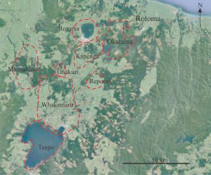
Approximate boundaries of major calderas in the active Taupo Volcanic Zone, New Zealand. Okataina eruption centre and Lake Rotoma are located in the northeast corner. Base map from Google Earth. Caldera boundaries from Leonard et al. 2010.

Approximate boundaries of major calderas in the active Taupo Volcanic Zone, New Zealand. Okataina eruption centre and Lake Rotoma are located in the northeast corner. Base map from Google Earth. Caldera boundaries from Leonard et al. 2010.

Rhyolitic and dacitic lava, pyroclastics, and airfall deposits are exposed in road cuts and along the shore of Lake Rotoma, formed about 7000-9000 years ago. The lavas are flow banded and contain abundant spherulitic obsidians. Pyroclastics include partly welded and non-welded ignimbrites, and block and ash flow deposits; at one locality the BAFs are sandwiched between flow banded rhyolite. Lava flows and PDCs are also draped by airfall deposits.

A block and ash flow derived from dome collapse at Mt. Tarawera. Note the angularity of blocks and coarse lapilli (to 50 cm wide in this view), extremely poor sorting, and lack of preferred clast alignment. The stratified ash beneath the BAF may be a surge deposit. Hammer lower centre. Image credit: Tarawera, Kari Cooper, 2017, National Science Foundation, public domain

A block and ash flow derived from dome collapse at Mt. Tarawera. Note the angularity of blocks and coarse lapilli (to 50 cm wide in this view), extremely poor sorting, and lack of preferred clast alignment. The stratified ash beneath the BAF may be a surge deposit. Hammer lower centre. Image credit: Tarawera, Kari Cooper, 2017, National Science Foundation, public domain.


Left: Flow banded rhyolite and black obsidians stratigraphically associated with the BAF deposits shown in the image below. Right: Black spherulitic obsidian. The spherulites are spheroidal to oblate and consistently 2-3 mm in diameter. Both lithologies comprise the dominant fragmental rock types in the associated BAFs. Coin diameter is 22 mm. Southwest shore of Lake Rotoma, New Zealand.

Left: Flow banded rhyolite and black obsidians stratigraphically associated with the BAF deposits shown in the image below. Right: Black spherulitic obsidian. The spherulites are spheroidal to oblate and consistently 2-3 mm in diameter. Both lithologies comprise the dominant fragmental rock types in the associated BAFs. Coin diameter is 22 mm. Southwest shore of Lake Rotoma, New Zealand.


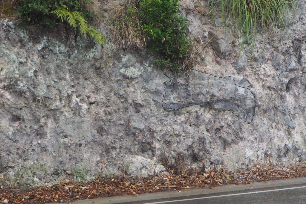
Block and ash flow deposit containing blocks and lapilli of dense rhyolite and flow banded obsidian. Note the 1.7 m long block at right centre (outlined). The deposit is very poorly sorted and lacks stratification or clast-size grading. Southwest shore of Lake Rotoma, New Zealand.

Block and ash flow deposit containing blocks and lapilli of dense rhyolite and flow banded obsidian. Note the 1.7 m long block at right centre (outlined). The deposit is very poorly sorted and lacks stratification or clast-size grading. Southwest shore of Lake Rotoma, New Zealand.


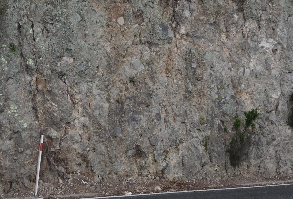
An example of a fines-depleted BAF containing a chaotic assortment of blocks ranging from lapilli-sized to about a metre diameter. Sorting is extremely poor; blocks are angular. The framework is mostly clast-supported. There is no preferred alignment of clasts. Block compositions include abundant flow banded rhyolite and obsidian. Detailed views are shown in the two images below. The road marker is 1 m long. South shore of Lake Rotoma.

An example of a fines-depleted BAF containing a chaotic assortment of blocks ranging from lapilli to about a metre diameter. Sorting is extremely poor; blocks are angular. The framework is mostly clast-supported. There is no preferred alignment of clasts. Block compositions include abundant flow banded rhyolite and obsidian. Detailed views are shown in the two images below. The road marker is 1 m long. South shore of Lake Rotoma.


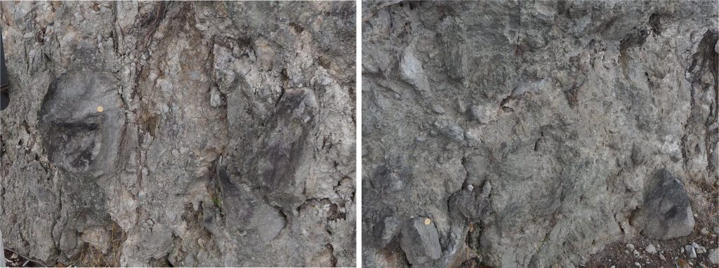
A closer look at the previous BAF example, emphasizing the clast-supported textures. Flow banding is visible in some obsidian and rhyolite blocks. This outcrop also contains significant fracturing – possibly caused by local tectonism during various eruptions, and/or by differential compaction from overlying flows and pyroclastics. Coin is 22 mm diameter. South shore of Lake Rotoma.

A closer look at the previous BAF example, emphasizing the clast-supported textures. Flow banding is visible in some obsidian and rhyolite blocks. This outcrop also contains significant fracturing – possibly caused by local tectonism during various eruptions, and/or by differential compaction from overlying flows and pyroclastics. Coin is 22 mm diameter. South shore of Lake Rotoma.


Another example of a fines poor BAF, this one sandwiched between flow banded rhyolites – that represent either lava flows or segments of lava domes. The base of the overlying flow has incorporated some blocks and sediment from the BAF (arrows). Outcrop is about 5 m high. Southeast shore of Lake Rotoma.

Another example of a fines poor BAF, this one sandwiched between flow banded rhyolites – that represent either lava flows or segments of lava domes. The base of the overlying flow has incorporated some blocks and sediment from the BAF (arrows). Outcrop is about 5 m high. Southeast shore of Lake Rotoma.


Related posts

Accretionary aggregates and accretionary lapilli

Ignimbrites in outcrop and thin section

Volcanics in outcrop: Pyroclastic density currents

Volcanics in outcrop: Secondary volcaniclastics

Volcanics in outcrop: Lava flows

Volcanics in outcrop: Pyroclastic fall deposits

Fluid flow: Froude and Reynolds numbers

Sediment transport: Bedload and suspension load

The hydraulics of sedimentation: Flow regime
Facebooktwitterlinkedininstagram
Facebooktwitterlinkedin

Ignimbrites in outcrop and thin section

Facebooktwitterlinkedininstagram
Multiple flow units in a Mid Miocene welded ignimbrite, Chilean Altiplano.

Multiple flow units in a Mid Miocene welded ignimbrite, Chilean Altiplano.

Ignimbrite is a rock name. Ignimbrites form primarily from the collapse of eruption columns during explosive volcanism and are included in the general category of ground-hugging pyroclastic density currents (PDC). Our collective observations of PDCs over the last few centuries shows them forming primarily from explosive vulcanian and plinian eruptions that, on a human scale, have proven to be violent and destructive – witness the eruption of Mt. Vesuvius and burial of Pompeii in 79 AD (Giacomelli et al., 2003; PDF), Mt. Pelée and the destruction of Saint-Pierre in 1902 (Gueugneau et al, 2020; open access), and Pinatubo in 1991 (PDCs, airfall, and lahars).

And yet, as destructive as these recent eruptions were, they are minuscule compared to many ancient examples of thick, extensive ignimbrites that must have formed from supereruptions of cataclysmic proportions – some not so ancient; the Taupo supereruption was a mere 1800 years ago, the Oruanui (Taupo) event 26,500 years ago (Wilson et al, 2006). The shear power and violence of this type of eruption is difficult to comprehend.

The original definition of ignimbrite by P. Marshall (1932, 1935 paper reproduced here),  based on a comparison of New Zealand examples with past events in the Valley of Ten Thousand Smokes, incorporated field-based criteria such as thickness, relationship to topography (do the deposits thicken in valleys?), consist primarily of juvenile pumice and ash, and the presence of welding. For many years welding was considered a prerequisite for ignimbrite status.

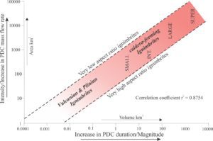
The decades following Marshall’s inspired investigations saw the term ignimbrite extended to all manner of pyroclastic flows – thick, thin, laterally extensive or of more local distribution, hot or cold including those that are not welded (e.g., the 26.5 thousand year old Oruanui ignimbrite, Taupo, Wilson et al., 2006; PDF). Giordano and Cas (2021) have attempted to rationalize this general terminological conflation with the following definition: an ignimbrite is “…the rock or deposit formed from pumice and ash- through to scoria and ash-rich pyroclastic density currents” regardless of thickness, areal extent, volume, composition, crystal content, relationship with topography, or temperature. This sounds like an anything-goes kind of definition, but Giordano and Cas also develop an ignimbrite classification scheme that distinguishes those formed from single vent eruptions (vulcanian and plinian, like Vesuvius and Pinatubo), from those of much greater magnitude and intensity that form during caldera collapse (issuing from multiple vents/fissures that ring the caldera); their diagram is reproduced below. This categorization is based on measurable quantities such as thickness, areal extent (flow run-out), volume, and aspect ratio. Dispersal area is controlled by the mass flow rate during an eruption and is a proxy for eruption intensity; likewise, flow volume is controlled by flow rate and the duration of the eruption and is a proxy for eruption magnitude.

Classification of ignimbrites formed from single vent eruptions, and the spectrum of multiple vents or fissures associated with caldera collapse, of increasing eruption intensity and magnitude. Redrawn from Giordano and Cas, 2021.

[Aspect ratio is calculated as the average thickness versus the average lateral extent. The concept was introduced to volcanology by George Walker (1983) to distinguish the conditions that create ignimbrites (explosivity, eruption magnitude and intensity)]

[Eruption intensity refers to the rate at which the pyroclastic mass is ejected]

[Eruption magnitude refers to the total mass erupted – the scale of erupted volumes is also encapsulated in the Volcanic Explosivity Index, or VEI]


Common ignimbrite traits

The following list is based primarily on field and petrographic characteristics. In addition to the references cited, I have also drawn on the chapter on ignimbrites by Freundt et al., 2000 (Encyclopedia of Volcanology).

  • Deposit thicknesses range from decimetres to 200 m and more. Thickness can be variable even within single flow units.
  • Their distribution is largely determined by topography, thickening in topographic lows and thinning over ridges. Their geometry reflects the dominant control of gravity from collapsing eruption columns. Individual flows are capable of blanketing landscapes for 10s of 1000s km2.
  • Calculation of the volume erupted needs to account for magma fragmentation, loss of volatiles, and the amount of fine ash dispersed far beyond the observed area of dispersal. It also needs to account for differences in pumice and glassy ash density compared with the equivalent dense, non-fragmented rock (i.e., solid lava). Therefore, erupted volumes are commonly quoted in terms of their dense-rock equivalent (DRE) – i.e., the equivalent volume of non-fragmented lava that in most cases would be rhyolite or dacite.
  • Thick ignimbrites commonly appear massive, but on close inspection may reveal several stacked flow or cooling units separated by co-ignimbrite airfall tephra, thin pyroclastic surge deposits, or abrupt changes in grain size or crystal concentrations and composition.
  • Grain size grading and stratification may develop in the upper and distal parts of flow units, reflecting waning turbulence in the former, and the transition to laminar fluid flow in the latter.
  • Most ignimbrites have rhyolite through dacite compositions. They have an abundance of juvenile pumice, crystals, and pyroclasts of all sizes, although fine ash to coarse lapilli are more common. The term juvenile refers to derivation from the erupted magma.
  • Within single flow units, crystal and pyroclast compositions may vary vertically and laterally. Some ignimbrites are crystal-phenocryst rich, others are crystal-poor. Such variations reflect the availability of materials in the magma, particularly as the magma chamber empties. Very large eruptions (supereruptions) may tap more than one magma chamber, and the magma composition in each may vary. This variation is reflected in the compositional zonation within and among closely spaced flow units, although mechanical winnowing of some crystal phases may also take place in the eruption column and ensuing PDC (see Wilson et al, 2021 for an excellent review of magma chamber evolution).
  • Phenocrysts are commonly broken by the intensity of the eruption and by mechanical diminution during turbulent pyroclastic flow.
  • Country rock derived from vent or fissure walls, or plucked from the substrate beneath a PDC may be added to the volcaniclastic mix.
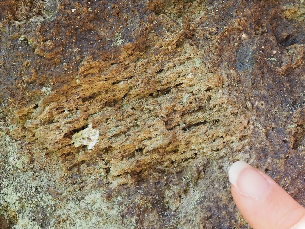
  • Welding is regarded as a syndepositional process. Welding, (also referred to as sintering) of pumice clasts and glass shards occurs when an ignimbrite is hot enough for glass to maintain a relatively fluid or ductile state during deposition. Experimental data on glass rheology indicates that temperatures greater than 800oC are required for this to take place (Lavallee et al. 2015; open access). Welding results in compression and stretching of pumice clasts, producing flame-like structures, or fiamme. Welding of finer ash produces agglutinated glass shards that, at a microscopic scale, appear to flow around phenocrysts and larger pyroclasts. Welding may be sufficiently pervasive to produce crude banding or layering (also called eutaxitic texture) that resembles flow-banding in felsic lava flows. Note that this kind of layering is not the same as that produced by laminar fluid flow in some PDCs.
  • Eutaxitic textures, a term usually reserved for welded ignimbrites, refers to the layering produced by the flattening and collapse of pumice fragments, and the agglutination of glass shards during sintering.
  • Columnar cooling joints are common in thick ignimbrites.
  • Porous, non-welded ignimbrites are susceptible to fumarolic alteration of glass and phenocrysts during cooling.

Ignimbrites in outcrop

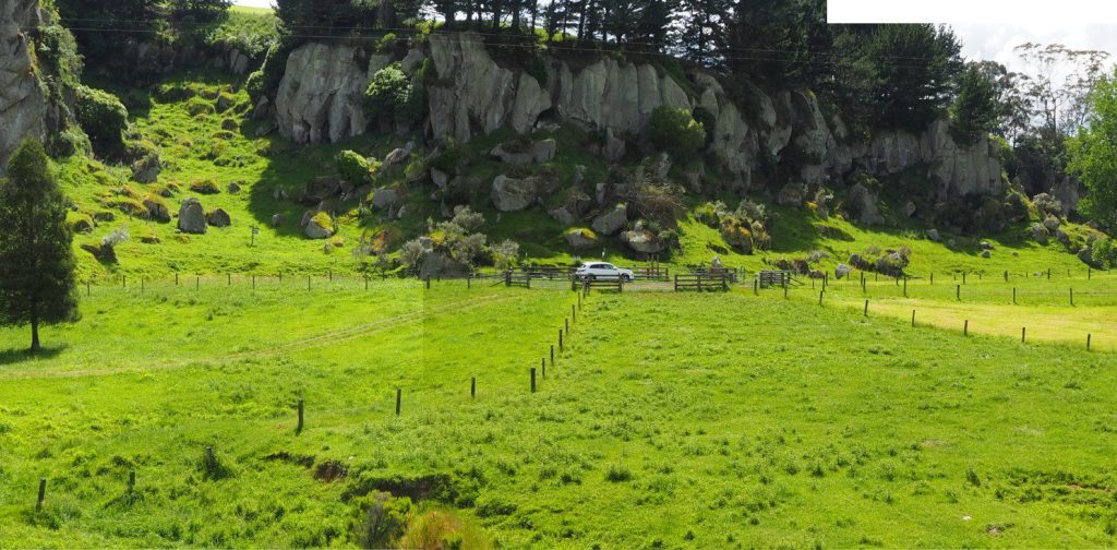
A panorama of the 1.21 Ma Ongatiti rhyolite-rhyodacite ignimbrite (Waikato, New Zealand), at least 11 m thick (base not exposed). At this locality (Castle Rock) there is no indication of extensive welding. At other localities, this ignimbrite is welded and contains several flow units ( Briggs et al., 1993) – see the thin section examples of welding in this ignimbrite. Elsewhere the ignimbrite thickens to 35 m and more. The eruption centre was the Mangakino Caldera (Taupo Volcanic Zone), about 20 km south of these cliffs. The dense-rock equivalent volume (DRE) is more than 500 km3.

A panorama of the 1.21 Ma Ongatiti rhyolite-rhyodacite ignimbrite (Waikato, New Zealand), at least 11 m thick (base not exposed). At this locality (Castle Rock) there is no indication of extensive welding. At other localities, this ignimbrite is welded and contains several flow units ( Briggs et al., 1993) – see the thin section examples of welding in this ignimbrite. Elsewhere the ignimbrite thickens to 35 m and more. The eruption centre was the Mangakino Caldera (Taupo Volcanic Zone), about 20 km south of these cliffs. The dense-rock equivalent volume (DRE) is more than 500 km3.

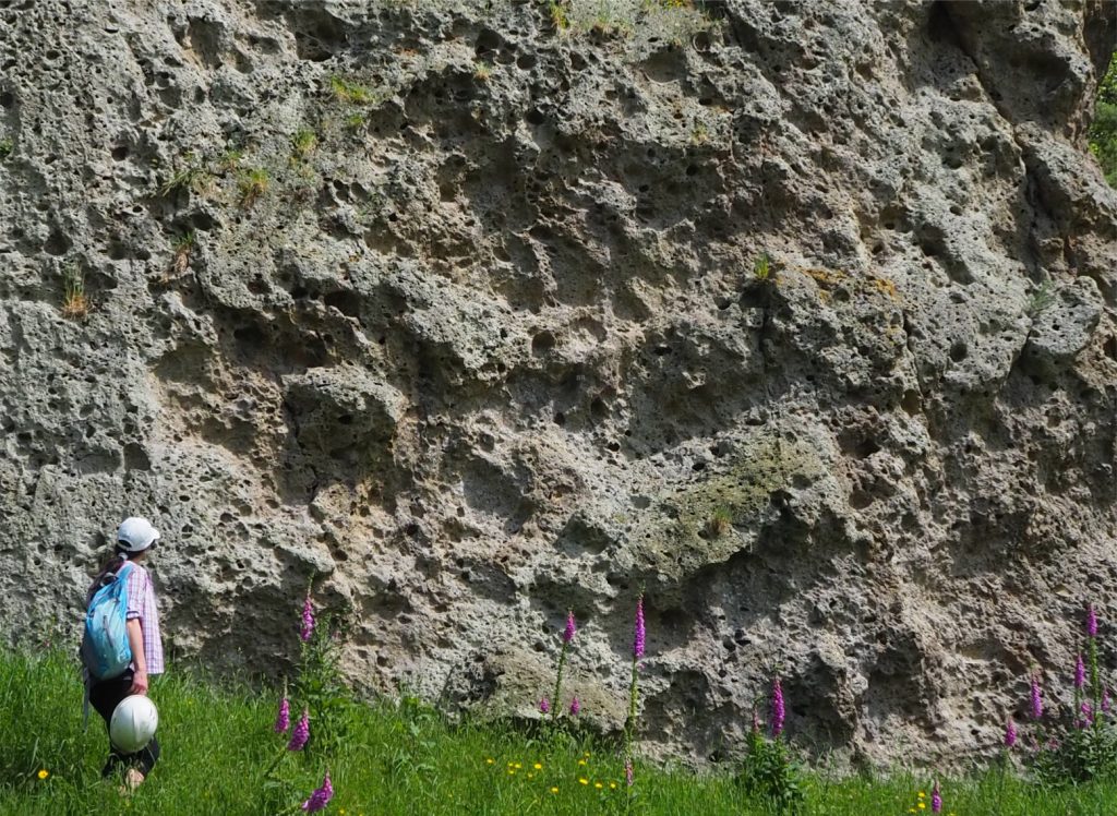
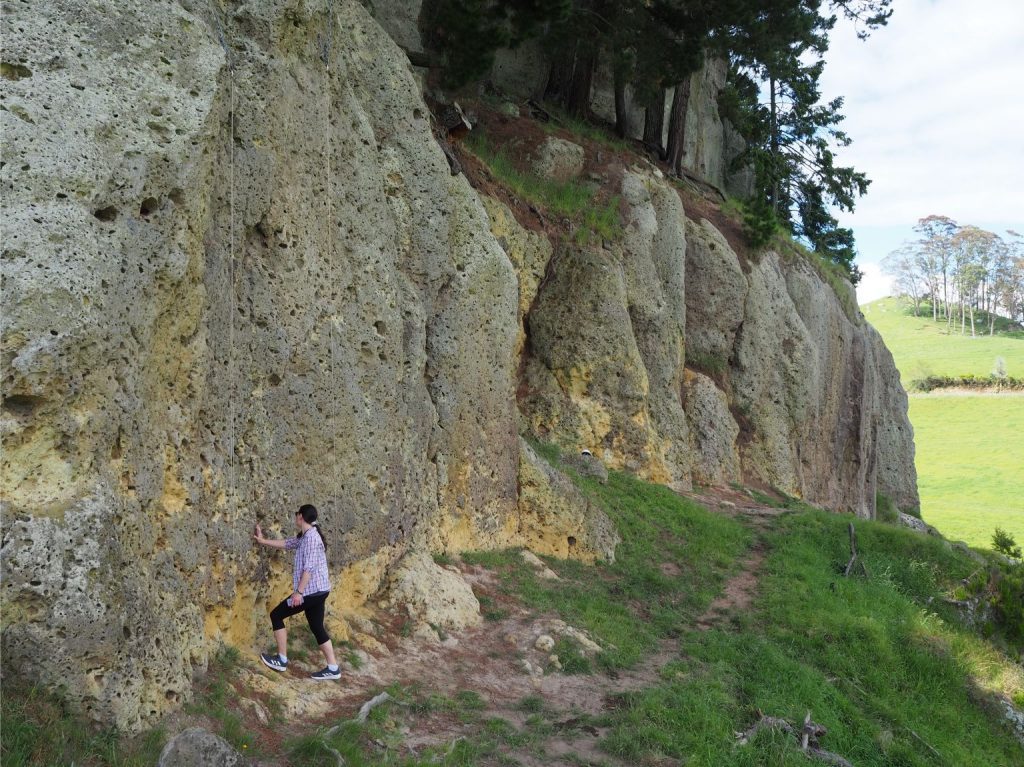
Typical weathered, pockmarked exposure of the Ongatiti Ignimbrite. The ‘holes’ are formed where soft pumice clasts are removed by weathering – giving us a good visual indication of their abundance. The largest clasts here have 40 mm long axes. Clast size sorting is extremely poor. Ignimbrite bluffs in this area are popular with rock climbers.

Janine Krippner is intrigued by this pockmarked exposure of the Ongatiti Ignimbrite. The ‘holes’ are formed where soft pumice clasts are removed by weathering – giving us a good visual indication of their abundance. The largest clasts here have 40 mm long axes. Clast size sorting is extremely poor. Ignimbrite bluffs in this area are popular with rock climbers.


A relatively intact, non-sintered pumice clast with preserved vesicles (there is some iron oxide alteration), Ongatiti Ignimbrite (location as above).

A relatively intact, non-sintered pumice clast with preserved vesicles (there is some iron oxide alteration), Ongatiti Ignimbrite (location as above).


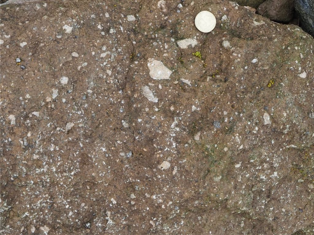
Non- to weakly welded, fine lapilli-sized pumice and rhyolite pyroclasts dispersed in much finer grained glassy ash. Note the variation in shape and angularity, and extremely poor sorting. Part of the Okataina Caldera (about 320 ka) exposed along the shore and road cut of Lake Rotoma. Taupo Volcanic Zone, New Zealand. Coin is 23 mm diameter.

Non- to weakly welded, fine pumice and rhyolite lapilli dispersed in much finer grained glassy ash. Note the variation in shape and angularity, and extremely poor sorting. Part of the Okataina Caldera (about 320 ka) exposed along the shore and road cut of Lake Rotoma. Taupo Volcanic Zone, New Zealand. Coin is 23 mm diameter.


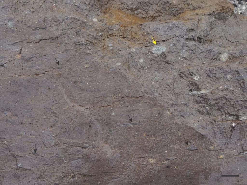
Welded ignimbrite exposed along the faulted shoreline margin of Lake Rotoma, part of the Okataina Volcanic Centre (about 320 ka). Most pumice fragments are stretched and flattened (arrows) but a few denser varieties are unchanged (yellow arrow). The ignimbrites are intercolated with flow banded rhyolites, obsidians, and coarse breccias. Taupo Volcanic Zone, New Zealand. Bar scale 30 mm.

Welded ignimbrite exposed along the faulted shoreline margin of Lake Rotoma, part of the Okataina Volcanic Centre (about 320 ka). Most pumice fragments are stretched and flattened (arrows) but a few denser varieties are unchanged (yellow arrow). The ignimbrites are intercolated with flow banded rhyolites, spherulitic obsidian, and coarse breccias. Taupo Volcanic Zone, New Zealand. Bar scale 30 mm.


Intensely welded, flattened, and stretched pumice fragments forming typical fiamme. Welding is pervasive in this ignimbrite, part of the Late Pliocene Coroglen Subgroup, exposed north of Whiritoa, Coromandel Volcanic Zone.

Intensely welded, flattened, and stretched pumice fragments forming typical fiamme. Welding is pervasive in this ignimbrite, part of the Late Pliocene Coroglen Subgroup, exposed north of Whiritoa, Coromandel Volcanic Zone.


The Mamaku Ignimbrite (240,000 yr) was one of the main eruptive products during the Late Pleistocene caldera collapse that formed Lake Rotorua. The upper, non-welded portion of the PDC was subjected to fumarolic discharge during cooling that resulted in pockets of cement hardened deposits. Subsequent erosion removed the soft, non-cemented ignimbrite, leaving upstanding remnants of the hardened rock preserved as steep-sided mounds capped by rocky spires and blocks. These landforms are called Tors, or Inselbergs. The top of the Mamaku Ignimbrite is littered with tors - shown in this Google Earth image. Taupo Volcanic Zone, New Zealand.

The Mamaku Ignimbrite (240,000 yr) was one of the main eruptive products during the Late Pleistocene caldera collapse that formed Lake Rotorua. The upper, non-welded portion of the PDC was subjected to fumarolic discharge during cooling that resulted in pockets of cement hardened deposits. Subsequent erosion removed the soft, non-cemented ignimbrite, leaving upstanding remnants of the hardened rock preserved as steep-sided mounds capped by rocky spires and blocks. These landforms are called Tors, or Inselbergs. The top of the Mamaku Ignimbrite is littered with tors – shown in this Google Earth image. Taupo Volcanic Zone, New Zealand.


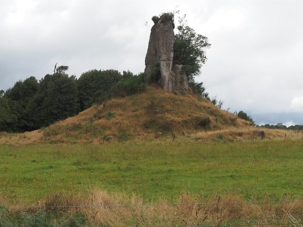
A tor at the top of the Mamaku Ignimbrite (west of Rotorua). The mound and spire are about 9m high. The general relief here also indicates the amount of denudation since ignimbrite emplacement. Taupo Volcanic Zone, New Zealand.

A tor at the top of the Mamaku Ignimbrite (west of Rotorua). The mound and spire are about 9m high. The general relief here also indicates the amount of denudation since ignimbrite emplacement. Taupo Volcanic Zone, New Zealand.


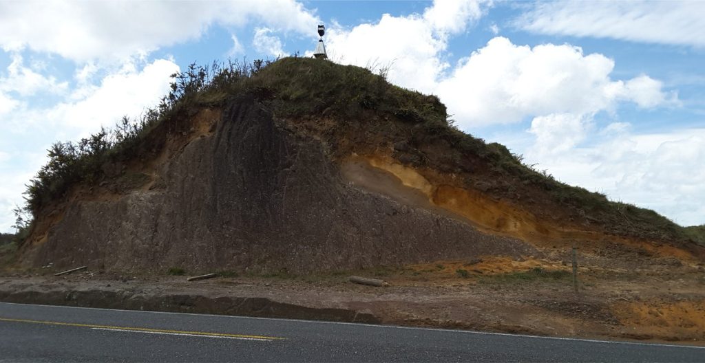
Road cut through a Mamaku Ignimbrite tor (Hwy 5, west of Rotorua). The eroded top of the Ignimbrite is draped by younger airfall tephra. See Google Earth image above for location. Taupo Volcanic Zone, New Zealand.

Road cut through a Mamaku Ignimbrite tor (Hwy 5, west of Rotorua). The eroded top of the Ignimbrite is draped by younger airfall tephra. See Google Earth image above for location. Taupo Volcanic Zone, New Zealand.


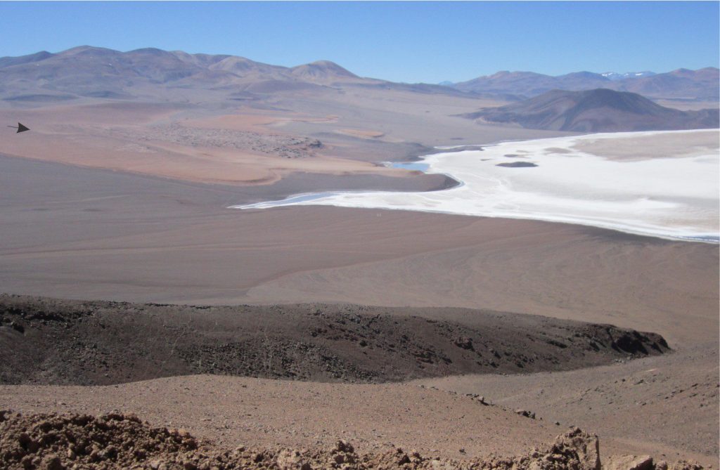
Eroded remnants of a Middle Miocene welded ignimbrite bordering Salar LaGrande, Chilean Altiplano (orange hues, arrow top left). The high ground behind the ignimbrite is mostly composite andesitic and basaltic cones of similar age. The eruptive episodes were associated with Mid-Miocene caldera collapse. The ignimbrite is lapped by more recent, arid, alluvial fans, the alluvium derived from Mid Miocene basalts and andesites. The Salar is capped by thick (white) gypsum and halite crusts.

Eroded remnants of a Middle Miocene welded ignimbrite bordering Salar La Grande, Chilean Altiplano (orange hues, arrow top left). The high ground behind the ignimbrite is mostly composite andesitic and basaltic cones of similar age. The eruptive episodes were associated with Mid-Miocene caldera collapse. The ignimbrite is lapped by more recent, arid, alluvial fans, the alluvium derived from Mid Miocene basalts and andesites. The Salar is capped by thick (white) gypsum and halite crusts.


The ignimbrite (same unit as image above) is composite, consisting of overlapping flow units (white arrows) separated by subtle changes in pumice and crystal content, the contacts weathering out as apparent horizontal joints. About 5 m of section in this view. In the background, a nicely preserved Middle Miocene volcanic cone, plus a peekaboo view of Salar LaGrande.

The ignimbrite (same unit as image above) is composite, consisting of overlapping flow units (white arrows) separated by subtle changes in pumice and crystal content, the contacts weathering out as apparent horizontal joints. About 5 m of section in this view. In the background, a nicely preserved Middle Miocene volcanic cone, plus a peekaboo view of Salar La Grande.

A closer look at the welded, flattened pumice, accentuated by weathering (same unit as image above). There is a crude alignment of the flattened clasts. Hammer lower left.

A closer look at the welded, flattened pumice, accentuated by weathering (same unit as image above). There is a crude alignment of the flattened clasts. Hammer lower left.

Ignimbrites in thin section

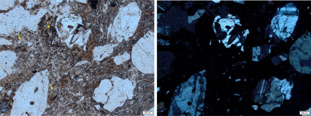
Welded 1.21 Ma Ongatiti Ignimbrite (located in a quarry at Hinuera). Left: Broken plagioclase phenocrysts are surrounded by flattened and stretched glass shards – compression has produced flow patterns around the crystals. The remnants of bubble-wall textures are seen in some shards (arrows). Plain polarized light. Right: The glass component is isotropic under crossed polars.

Welded 1.21 Ma Ongatiti Ignimbrite (located in a quarry at Hinuera). Left: Broken plagioclase phenocrysts are surrounded by flattened and stretched glass shards – compression has produced flow patterns around the crystals. The remnants of bubble-wall textures are seen in some shards (arrows). Plain polarized light. Right: The glass component is isotropic under crossed polars.


Welded Ongatiti Ignimbrite (same location as above). Prominent flow textures and flattening of glass shards occurred while the glass temperature was high enough to sustain ductile behaviour. The ragged phenocrysts are plagioclase, broken during eruption or during turbulent transport in the PDC. Plain polarized light.

Welded Ongatiti Ignimbrite (same location as above). Prominent flow textures and flattening of glass shards occurred while the glass temperature was high enough to sustain ductile behaviour. The ragged phenocrysts are plagioclase, broken during eruption or during turbulent transport in the PDC. Plain polarized light.


Intensely welded Matahina Ignimbrite (322 ka), part of the Okataina Volcanic centre. Taupo Volcanic Zone, New Zealand. The glass appears fuzzy (in PPL) because it has been altered by fumarolic activity during the post-depositional cooling phase. The phenocrysts are a mix of broken and complete crystals. Left: Plain polarized light. Right: Crossed polars. Note the preserved crystal faces on the plagioclase top left (p). Of the two broken plagioclase fragments, one is zoned (z), the other untwinned (it has good cleavage). There is a single, small pyroxene (px). The squiggly crystal at bottom centre may be a resorbed plagioclase (r): it has cleavage, but no twinning. Resorption occurs when there is disequilibrium between the magma melt and the solid crystal phase.


Pumice fragment showing good preservation of vesicles. Plain polarized light. Taupo Volcanic Zone, New Zealand.

Pumice fragment showing good preservation of vesicles. Plain polarized light. Taupo Volcanic Zone, New Zealand.


A seriously sintered, flattened pumice fragment, with collapsed vesicles. The fractured quartz phenocryst probably indented the pumice fragment during compression while the glass was still relatively fluid. Individual glass shards in the surrounding ash have also been welded together forming pronounced eutaxitic texture. Waiotapu Ignimbrite (710 ka). Taupo Volcanic Zone, New Zealand. Plain polarized light.

A seriously sintered, flattened pumice fragment, with collapsed vesicles. The fractured quartz phenocryst probably indented the pumice fragment during compression while the glass was still relatively fluid. Individual glass shards in the surrounding ash have also been welded together forming pronounced eutaxitic texture. Waiotapu Ignimbrite (710 ka). Taupo Volcanic Zone, New Zealand. Plain polarized light.


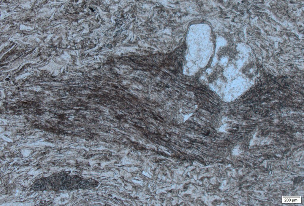
The rheology of volcanic glass during intense sintering is nicely illustrated here with flow and compression around a quartz phenocryst (lower centre). Most of the glass shards have been flattened. The glass in this and the previous image has been devitrified. Waiotapu Ignimbrite (710 ka). Taupo Volcanic Zone, New Zealand. Plain polarized light.

The rheology of volcanic glass during intense sintering is nicely illustrated here with flow and compression around a quartz phenocryst (lower centre). Most of the glass shards have been flattened. The glass in this and the previous image has been devitrified. Waiotapu Ignimbrite (710 ka). Taupo Volcanic Zone, New Zealand. Plain polarized light.


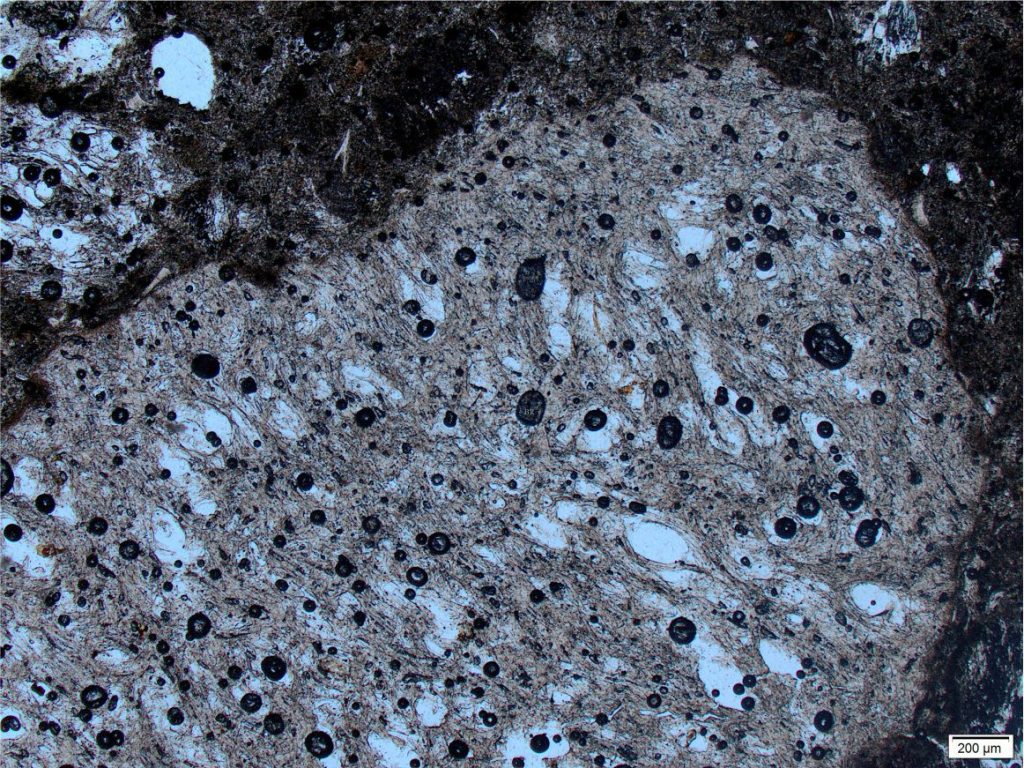
Fresh pumice from the Taupo supereruption, about 1800 years ago. No welding or compaction. The fragment is basically a collection of vesicles held together by a glass lacework. Plain polarized light. Taupo Volcanic Zone, New Zealand.

Fresh pumice from the Taupo supereruption, about 1800 years ago. No welding or compaction. The fragment is basically a collection of vesicles held together by a glass lacework. Plain polarized light. Taupo Volcanic Zone, New Zealand.


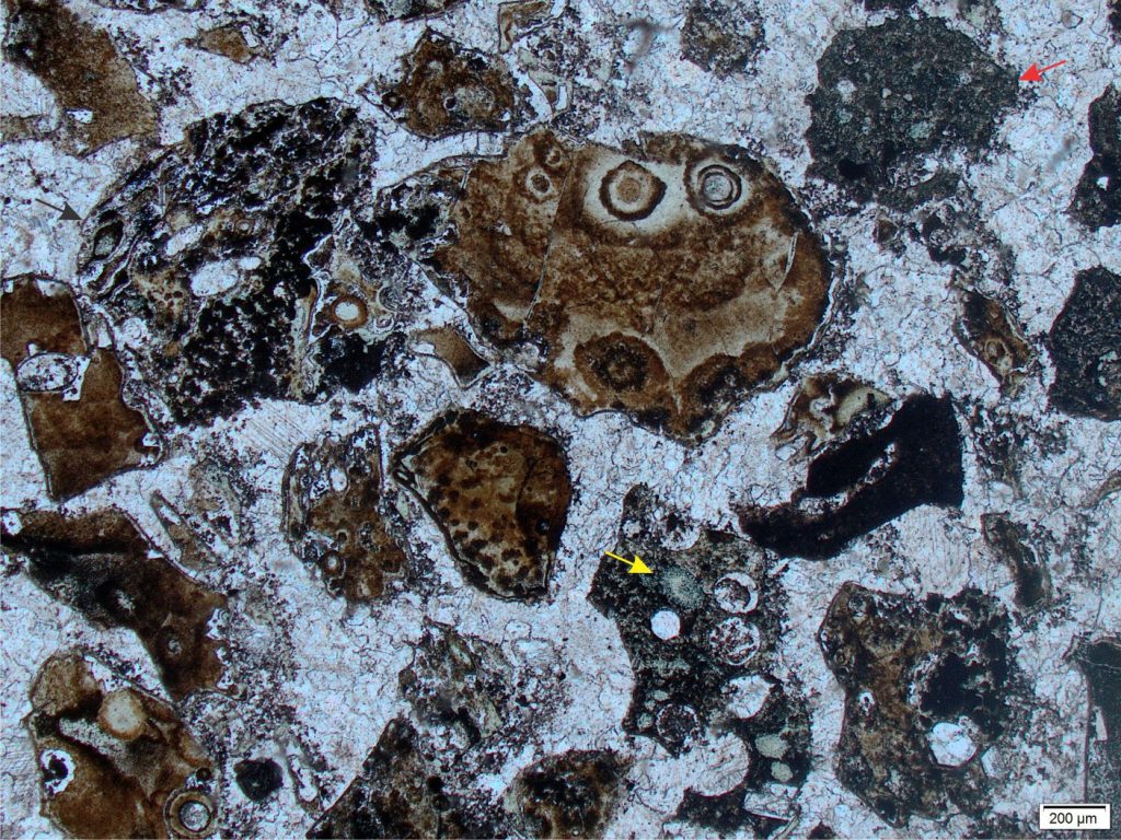
Pumice fragments from a thick PDC in the Paleoproterozoic Flaherty Fm. Belcher Islands. The associated volcanics (lava flows and pillow lavas) are basaltic and at least partly submarine. There is no indication of sintering. One clast has elongated vesicles and small, black, opaque hematite crystals (top left, arrow). Vesicles are filled with chlorite (yellow arrow) and calcite; the main cement is calcite. There are a few grains of altered basalt (red arrow). The original glass has been replaced by Fe oxides. Plain polarized light.

Pumice fragments from a thick PDC in the Paleoproterozoic Flaherty Fm. Belcher Islands. The associated volcanics (lava flows and pillow lavas) are basaltic and at least partly submarine. There is no indication of sintering. One clast has elongated vesicles and small, black, opaque hematite crystals (top left, arrow). Vesicles are filled with chlorite (yellow arrow) and calcite; the main cement is calcite. There are a few grains of altered basalt (red arrow). The original glass has been replaced by Fe oxides. Plain polarized light.

Acknowledgement

Many thanks to Kirsty Vincent, Earth Sciences, Waikato University for access to the petrographic microscope.

Related posts

Accretionary aggregates and accretionary lapilli

Block and ash flows

Ignimbrites in outcrop and thin section

Volcanics in outcrop: Pyroclastic density currents

Volcanics in outcrop: Secondary volcaniclastics

Volcanics in outcrop: Lava flows

Volcanics in outcrop: Pyroclastic fall deposits

Fluid flow: Froude and Reynolds numbers

Sediment transport: Bedload and suspension load

The hydraulics of sedimentation: Flow regime
Facebooktwitterlinkedininstagram
Facebooktwitterlinkedin

Volcanics in outcrop: Pyroclastic density currents

Facebooktwitterlinkedininstagram
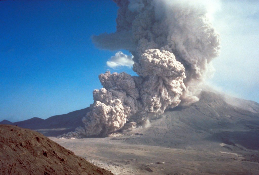
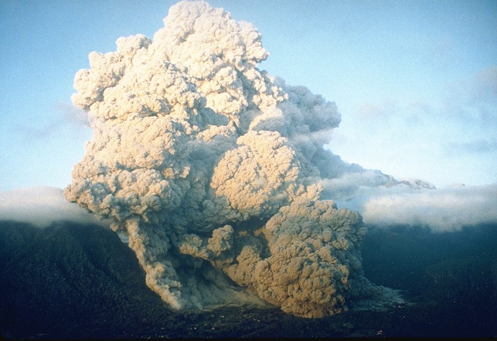
A ground-hugging pyroclastic density current and associated buoyant plume generated by column collapse at Mt St. Helens August 7, 1980, almost 3 months after the devastating eruption and lateral blast (May 18). Image credit: Peter Lipman, USGS.

A ground-hugging pyroclastic density current and associated buoyant plume generated by column collapse at Mt St. Helens August 7, 1980, almost 3 months after the devastating eruption and lateral blast (May 18). Image credit: Peter Lipman, USGS.

This post continues the series on volcanic and volcaniclastic rocks in outcrop, with a brief introduction to pyroclastic density currents (PDCs).

It has become cliché to describe pyroclastic flows as hazardous to one’s health. I prefer a more colourful analogy found in a rewording of Tolkien’s description of the fire-breathing dragon Smaug the Terrible, voiced by Bofur the dwarf as “a flash of light, searing pain, and poof! You’re nothing more than a pile of ash.” – an analogy that paints a picture of instant incineration, laceration, and suffocation if confronted by a maelstrom of hot gas and razor-sharp fragments of volcanic glass. Distinctly unpleasant.

Pyroclastic density current (PDC) is the catch-all term to describe ground-hugging, gravity-driven mixtures of gas and volcaniclastic debris, derived from explosive eruptions. PDCs are fast moving (several 10s to 100s of km/hour), and invariably warm (up to 700o C – 1300oF). The term encompasses pyroclastic flows, ignimbrites, block and ash flows, pyroclastic surges, and base-flows (but not lahars). They all consist of fragmented, most commonly silicic magma, vent wall-rock, and ripped up substrate. They are two-phase systems, like much colder sediment gravity flows such as turbidity currents and debris flows, except the fluid phase in PDCs is a mix of water vapour, ingested air, and probably some CO2. Recent PDCs are mostly generated by explosive magmatic eruptions, but they are also known from violent phreatomagmatic events such as maar eruptions.

Our understanding of pyroclastic flows, their internal organisation, mechanisms of emplacement, and how these variables evolve as the flow progresses, is seriously hampered by our inability to get close enough for observation and measurement. We can establish their external organisation and geometry from direct observations (from afar) and videos of relatively small, recent flow events. Flow stratigraphy gives us snapshots in time of processes at the depositional surface, but not in the overlying flow. Numerical modelling can fill some of these knowledge gaps, but models also rely on real data for meaningful calibration.

However, all is not lost. Volcanologists have unashamedly borrowed (and subsequently modified) some well-established observational data and theory from our knowledge of ‘cold’ sediment gravity flows (i.e., turbidite currents, debris flows, and grain flows). Our understanding of sediment gravity flow mechanics has advanced from direct observation of cold flow events, a century of analogue modelling (e.g., flumes), plus conceptual and numerical models. We tend to think of support mechanisms in sediment gravity flows in terms of turbulence or laminar flow, matrix strength and viscosity (i.e., fluid rheology – is it acting like a hydroplastic or Newtonian fluid?), collisions among grains, buoyancy, and shear forces acting near the flow-substrate contact. These are all properties and processes that can be applied to models of pyroclastic flows, with the added complication of elevated temperature. Significantly, the last couple of decades have also seen the development of (cold) flume-like pyroclastic flow experiments in air, using volcanic granular material to simulate the characteristics of flow and the resulting stratigraphy (e.g., Lube et al., 2015; PDF available). Laser technology also provides us with the opportunity to look inside these experimental flows, to track particle trajectories along their journey from flow initiation to deposition.


Flow initiation

Eruption of Unzen Volcano (Kyushu, Japan) on June 23, 1993, destroyed the outer areas of Shimabara city. Image credit: Setsuya Nakada, Smithsonian Institution

Eruption of Unzen Volcano (Kyushu, Japan) on June 23, 1993, destroyed the outer areas of Shimabara city. Image credit: Setsuya Nakada, Smithsonian Institution

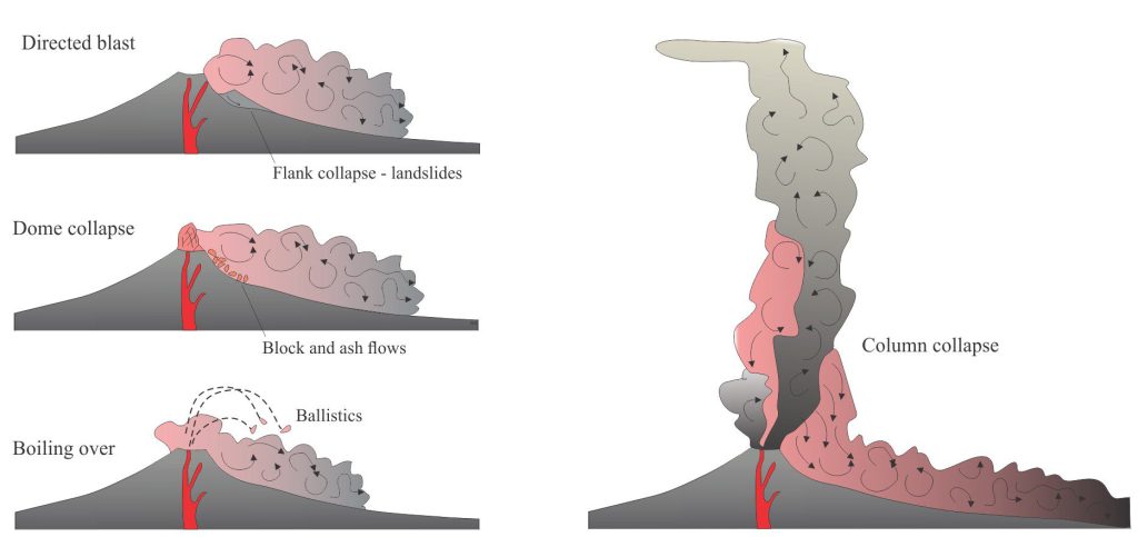
All pyroclastic flows are initiated by explosive eruptions from subaerial volcanic cones, maars, and collapsing calderas (see the diagram below). It is common for more than one mechanism to operate during an eruption episode (Belousov et al., 2007; PDF available). This was demonstrated by the 1980 Mt. St. Helens activity that showed us, perhaps more than any other recent event, that eruption mechanisms can evolve rapidly and devastatingly – in this case, from an initial upper-flank collapse and subsequent landslide to magma dome collapse that released a directed, lateral pyroclastic blast, and later collapse of plinian eruption columns.

Four eruption types that generate pyroclastic density currents. Eruption episodes commonly involve more than one type; such transitions can occur rapidly as was the case for the 1980 eruption episode at Mt. St. Helens, or over longer periods as magma production and eruption style evolve. Modified from Dufek et al., 2015, Fig. 35.1 (PDF available)

Four eruption types that generate pyroclastic density currents. Eruption episodes commonly involve more than one type; such transitions can occur rapidly as was the case for the 1980 eruption episode at Mt. St. Helens, or over longer periods as magma production and eruption style evolve. Modified from Dufek et al., 2015, Fig. 35.1 (PDF available)

Silicic domes that protrude from the crater or upper flank of a volcanic edifice grow relatively slowly by accretion of magma. The domes act like a pressure valve; they are inherently unstable gravitationally and because of elevated pressures. Breaching the valve (dome collapse) will release a blast of gas plus fragmented magma and cooled rock. Blasts that are directed laterally transform rapidly to pyroclastic flows. Recent examples are Mt. St. Helens and Soufriere Hills; both eruption episodes also included vulcanian and plinian columns that collapsed to produce pyroclastic flows. Directed blasts are usually associated with flank, sector, or magma dome collapse; flank collapse will also produce landslides. Initial blast velocities can be more than 350 km/hr.

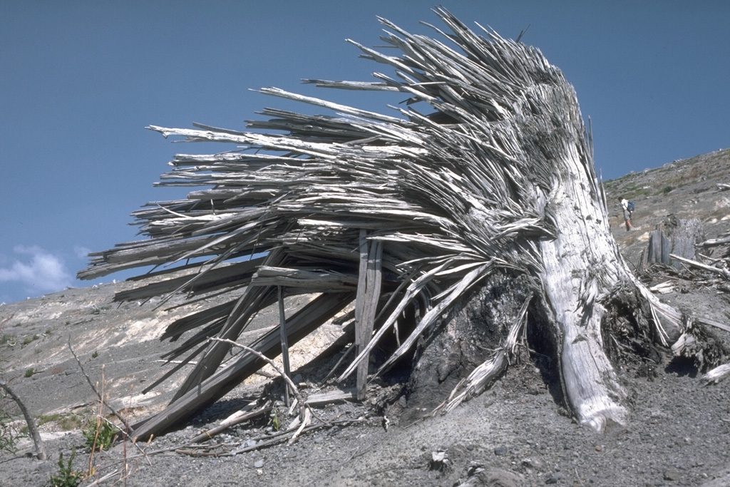
A classic image of the kind of devastation wrecked by a PDC, in this case the lateral blast that initiated the Mt. St. Helens eruption episode, May 18, 1980. This tree was about 9 km from the main crater. Image credit: Lee Siebert, 1984 (Smithsonian Institution)

A classic image of the kind of devastation wrecked by a PDC, in this case the lateral blast that initiated the Mt. St. Helens eruption episode, May 18, 1980. This tree was about 9 km from the main crater. Image credit: Lee Siebert, 1984 (Smithsonian Institution)

The boil over category refers to fountain ejection of fragmented magma over a crater rim. Little or no fragmental debris is supplied by plume collapse. Lava fountains produce all manner of ballistic melt ejecta that on impact form breadcrust and cow-pat bombs. PDCs formed from this material are concentrated in various kinds of ejecta.

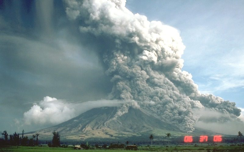
PDCs are also generated by column collapse when gravitational forces exceed the buoyancy of ash-rich ejecta. The size and runout of PDCs formed in this way depends on the size of the eruption column. Several PDCs can form at any time during an eruption, as new plumes form and earlier plumes collapse. The image of Mayon Volcano below (Sept. 23, 1984) shows at least 5 concurrent PDCs at different stages of development; the plume in this eruption reached an elevation of 15 km.

At least 5 concurrent PDCs at different stages of formation are captured in this image of the September 23, 1994 eruption of Mayon volcano, Philippines. Most of these flows have formed from collapse of the ash column. Image credit: C.G. Newhall, USGS

At least 5 concurrent PDCs at different stages of formation are captured in this image of the September 23, 1994 eruption of Mayon volcano, Philippines. Most of these flows have formed from collapse of the ash column. Image credit: C.G. Newhall, USGS

Parts of a flow – Inside PDCs

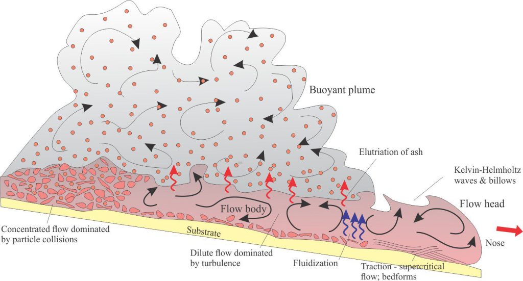
A schematic of flow support mechanisms, particle distributions, and depositional processes for a hypothetical pyroclastic density current. The diagram is intended to show the potential variability within a single flow and from one flow to the next. For example, concentrated flows may persist for an entire event, or transform to dilute flows, such as pyroclastic surges, over time.

A schematic of flow support mechanisms, particle distributions, and depositional processes for a hypothetical pyroclastic density current. The diagram is intended to show the potential variability within a single flow and from one flow to the next. For example, concentrated flows may persist for an entire event, or transform to dilute flows, such as pyroclastic surges, over time.

PDCs consist of two main components:

  • The main, ground-hugging body of the flow, which is denser than air, and
  • An overlying buoyant plume, less dense than air, that grows as fine ash elutriates from the main body of the flow.

The flow head is differentiated from the main body by the abrupt boundary between air and the billowing, turbulent mixture of gas and fragmental debris. Typically, the nose of the flow lifts above the substrate because friction along the substrate reduces the velocity relative to the overlying flow. This is also a common feature of cold sediment gravity flows (e.g., turbidity currents). Any erosion of the substrate probably takes place beneath the head.

The flow body is overlain by a buoyant plume. Some erosion may occur at the base but this part of a flow tends to be constructional because of sedimentation.

Particle concentration is highly variable among different PDCs and within a single PDC. Two end-member conditions, commonly defined as dilute flows (in which turbulence is the primary supporting mechanism) and concentrated flows (dominated by grain-to-grain collisions), are useful starting points for a description of PDCs. The concentration profile of a PDC may indicate either condition, or combinations where a basal layer contains high fragment concentrations overlain by a more dilute flow. Some flows retain their concentrated profiles throughout; deposition of coarse debris along levees is common on the margins of such flows.  In other PDCs, fragment concentration profiles change in the down-flow direction because the ingestion of air through the billowing flow-top in addition to particle deposition will both promote dilution.

Pyroclastic surges are typically dilute. A flow may begin life as a pyroclastic surge if initial particle concentrations are low, or it may evolve by progressive dilution of more concentrated flows. Sedimentation commonly involves bedload processes under supercritical flow conditions, resulting in a variety of low amplitude crossbeds and crossbed truncations.


Flow support mechanisms

Propagation of PDCs will continue only as long as there is a mechanism to support the suspension of fragmental debris. The most common mechanisms are turbulence, particle collisions, and fluid pressure and fluidization.

The development of turbulent flow is probably initiated immediately flow begins because velocities are high and viscosity is low (i.e., very high Reynolds Numbers). In dilute flows, turbulence will also be generated at the base of the flow because of substrate roughness (e.g. boulders that stand out), and by abrupt changes in topography. It has also been observed that near the flow head, intense shear at the contact between the rapidly moving flow and overlying air and will lead to Kelvin-Helmholtz instabilities, resulting in elutriates and billows; instabilities may also form at the contact between the body of a flow and its overlying buoyant plume. This transformation is analogous to the more familiar atmospheric Kelvin-Helmholtz waves, commonly manifested as mackerel skies and the gut-wrenching turbulence during air travel. The unstable boundary rapidly transforms to turbulence that promotes the ingestion of air into the flow body.

A mackerel sky, viewed from beneath – cloud waves generated by Kelvin-Helmholtz instabilities caused by shear of an overlying, fast-moving air mass over a slower moving, more dense cloud mass.

A mackerel sky, viewed from beneath – cloud waves generated by Kelvin-Helmholtz instabilities caused by shear of an overlying, fast-moving air mass over a slower moving, more dense cloud mass.

As flows progress, suspended fragments will lose momentum and become more concentrated near the flow base. Thus, flows become progressively more dilute and at some point, the mixture of gas and fine particles will become less dense than air, resulting in a buoyant plume above the main flow.

In the more concentrated parts of a flow, particularly at the base, interparticle collisions result in the transfer of momentum that helps to support the flow. However, each collision also results in the transfer of some kinetic energy to the gas phase; the gradual loss of momentum leads eventually to deposition.

Elevated fluid pressures (air plus water vapour) and will also play a role in supporting solid debris in the main body of a flow (pressure gradients will be directed from bottom to top). Incinerated vegetation and vapourized soil moisture may increase local fluid pressures at the flow base. The system will become fluidized if upwards fluid flow exceeds the gravitational forces acting on particles. Particles will fall out of fluid suspension once the elevated pressures have dissipated.

Evidence for post-depositional elevated fluid pressures is sometimes preserved as fluid escape pipes, which form where permeability barriers in the deposits cause local overpressured conditions.


At the depositional interface  

Volcanologists consider two end-member modes of deposition for PDCs – en masse freezing of the entire flow body, and incremental deposition on an aggrading bed. There is still debate over the relative importance of either mechanism.

The depositional record of PDCs is as variable as the flows themselves. Deposits may be massive, lacking any kind of stratification, massive but clast-size graded, stratified, or combinations that reflect changing particle concentrations and mechanisms of flow.

Massive deposits are perhaps the most difficult to interpret. Deposits like this may have formed by rapid deposition where turbulent sorting and grain entrainment were suppressed. However, if normal size grading is present, then turbulence has not been suppressed. Reverse grading, particularly of large pumice fragments, indicates that buoyancy forces were also important.

A more-or-less massive ignimbrite, at least 10 m thick (base not exposed) with no obvious stratification or clast-size grading. At this locality it is mostly nonwelded. The pits have formed by erosion of pumice fragments. This PDC is about 1.6 Ma.

A more-or-less massive ignimbrite, at least 10 m thick (base not exposed) with no obvious stratification or clast-size grading. At this locality it is mostly nonwelded. The pits have formed by erosion of pumice fragments. This PDC is about 1.6 Ma.

Stratification of any kind within a PDC implies that the forces of shear, friction, and fluid drag were operating along or close to the depositional surface. Processes that lead to bedload deposition include:

  • A traction carpet where grains roll, slide and jostle along the bed at a rate depending on flow velocity, fluid drag, and bed roughness (i.e., how many large bits get in the way), and
  • A saltation load, where fluid lift provides enough force for grains to temporarily leave the bed.

Stratified bedload deposits are relatively common in dilute PDCs where there is a constant supply of fragments falling out of the overlying turbulent suspension. Deposit thickness depends on the overall particle concentration and size of a flow. Low amplitude crossbeds and crossbed truncations appear to be a hallmark of pyroclastic surges. It is usually concluded that these bedforms develop under supercritical flow conditions given the inevitable high velocities of flow.

Typical bedforms deposited during supercritical flow of successive pyroclastic surges, La Breña maar, México. Note the well-defined stratification and partitioning of grain size among each lamination. Flow was to the left. Pen for scale (center). Image credit: Jim Luhr, 1988, Smithsonian Institution

Typical bedforms deposited during supercritical flow of successive pyroclastic surges, La Breña maar, México. Note the well-defined stratification and partitioning of grain size among each lamination. Flow was to the left. Pen for scale (center). Image credit: Jim Luhr, 1988, Smithsonian Institution

Related posts

Accretionary aggregates and accretionary lapilli

Ignimbrites in outcrop and thin section

Block and ash flows

Volcanics in outcrop: Secondary volcaniclastics

Volcanics in outcrop: Lava flows

Volcanics in outcrop: Pyroclastic fall deposits

Fluid flow: Froude and Reynolds numbers

Sediment transport: Bedload and suspension load

The hydraulics of sedimentation: Flow regime


A few sources of information

Excellent sources of PDC images available from the Smithsonian Institution gallery, and the USGS gallery.

Dufek et al., 2015 (PDF)Pyroclastic density currents: Processes and models. Chapter 35. An excellent summary.

Sulpizio et al., 2016. Pyroclastic density currents: state of the art and perspectives. Journal of Volcanology and Geothermal Research, Vol 283, Pages 36-65.

Giordano and Cas, 2021. Classification of ignimbrites and their eruptions. Earth Science Reviews, v 220, p.

Facebooktwitterlinkedininstagram
Facebooktwitterlinkedin

Volcanics in outcrop: Pyroclastic fall deposits

Facebooktwitterlinkedininstagram
Plinian eruptio of Raikoke

Plinian eruption of Raikoke volcano, Kuril Islands, June 22, 2019. Estimated height of the plume is 13-17 km. Umbrella region clearly developed where density of plume is the same as air density and plume stops rising. Downwind dispersal of the plume distributes fine ash over a wide area. Image credit: NASA Earth Observatory images by Joshua Stevens, Astronaut photograph ISS059-E-119250.

A look at volcaniclastics – pyroclastic fall deposits in outcrop

This is part of the How To… series  on describing rocks that in this post focuses on Primary  Volcaniclastics in outcrop. Although the series focuses on sediments and sedimentary rocks, I have added these posts on volcanics because of their importance to sedimentary basin dynamics and basin stratigraphy.

Ruapehu,  Tongariro, and Ngauruhoe, three active andesite stratovolcanoes in central North Island, New Zealand, are drawing cards for hikers, skiers and general hangers-on; hundreds of 1000s a year. On a foggy September night in 2007, a couple of hikers (sensibly) took shelter in a hut near the summit of Ruapehu. At 8.26 that evening, and with no warning, the volcano erupted explosively, not a large eruption, but violent enough to hurl ash and blocks up to 2km from the vent (Kilgour et al, 2010). One of those blocks crashed through the roof of the hut and crushed a leg of one hiker, narrowly missing the other person. Happily, both survived the ordeal, although one leg was lost.

The projectile that caused the damage was a large ballistic, a piece of rock fragmented by the wet (phreatomagmatic) eruption and thrown from the crater (that was also filled by a small lake), along with ash, lapilli, and lots of steam. Fragments of vent rock and magma formed by explosive eruptions are called pyroclasts. Pyroclasts are ejected from the vent in eruption columns and plumes, jets, and as ballistics.  Fragments of all sizes fall from the air under the influence of gravity; they accumulate as pyroclastic fall deposits.

Pyroclastic fall deposits are the product of three main kinds of eruption:

  1. Magmatic eruptions, where fragmentation results from extremely rapid decompression of gas in rising magma. Pyroclasts consist almost entirely of juvenile material derived from the magma.
  2. Phreatic eruptions; where rock heated by magma comes into contact with groundwater or seawater, but does not involve new magma (i.e. the magma itself does not erupt), and
  3. Phreatomagmatic eruptions, where rising magma comes into contact with water; the island Surtsey (Iceland) is an iconic example. (Houghton et al. 2015; Wilson et al, 2009). Hyalotuffs are the depositional product of phreatomagmatic eruptions. They tend to be glassy, and finer grained than magmatic eruptions because of the intense reaction between very hot magma and water.

Fragmental debris also forms when lava flows or is extruded into water (sea, lake) or beneath glaciers. In this situation, haloclastites form from thermal shock as the lava is rapidly chilled. They are common in pillow lavas. Hyaloclastites are not discussed further in this article.


Deposition

The trajectory and distance pyroclasts travel along a flight path depends mainly on:

  • The explosivity of the eruption (i.e. the amount of kinetic energy imparted). The degree of fragmentation also increases with explosivity – Strombolian fire- fountains contain a lot of lava spatter in contrast to Plinian eruptions that completely obliterate the original magma.
  • The height of the eruption column; higher columns tend to result in widespread distribution. This is particularly evident in the case of Plinian and ultraplinian eruptions with columns entering the upper troposphere.
  • The size and density of the fragments. Clast density (and composition) is usually constant during any single eruption but may change as the eruption cycle and magma composition evolve.
  • wind strength and direction at the time of the eruption.

Pyroclastic fall deposits also evolve from pyroclastic density currents (pyroclastic flows) when ash and lapilli are elutriated from the top of fast-moving flows. Deposits of this type are also called co-ignimbrite fall tephras.

Eruption style, fragmentation, pyroclast dispersal and volume are summarized in the diagram below, and keyed to the (log scale) Volcanic Explosivity Index (VEI). Descriptive terms are also applied to the various eruptions. Hawaiian eruptions are quiet or gentle, Vulcanian verge on the catastrophic, while Plinian and more energetic eruptions are frighteningly paroxysmic to colossal; Yellowstone supervolcano (632 Ka) falls into the latter category, as did Toba (northern Sumatra, 74Ka), and the most recent event at Taupo a mere 1800 years ago.

Eruption style and VEI

Comparison of principal eruption styles, their explosivity (VEI), dispersal and volumes. Information based on Newhall and Self, 1982; Newhall et al. 2018, and the USGS.

Attributes commonly used to identify fall deposits

(information from various sources, including Pierson et al, 2017; Houghton et al, 2015). The classification is that of White and Houghton, 2006.

1.   They tend to mantle topography. Compare this with fluvial reworked volcaniclastics, the locus of which is confined to topographic lows, and pyroclastic flows and surges that thin or pinch out over topographic highs. However, subsequent reworking of airfall tephras by precipitation runoff may preferentially erode material on elevated ground, depositing it in adjacent valleys.

Airfall and fluvial deposits, flank of Karioi, Raglan, NZ

Well-bedded airfall tephras mantle fluvial-reworked tephras and boulder avalanche deposits on the flank of the Pliocene stratovolcano Karioi, New Zealand.


Pliocene airfall tephras, Karioi, NZ

Thin bedded Pliocene airfall tephras mantle boulders that protrude from a pyroclastic surge deposit, Karioi, Raglan, New Zealand.

2.      Fall deposits are generally better sorted than other primary volcaniclastics. Sorting in this case is a function of gravitational settling, and the aerodynamic response to clast size, shape, and density.

3.    Bedding contacts are commonly abrupt. Beds will be thicker near the source, thinning downwind. Any crossbedding is likely associated with fluvial processes or pyroclastic surges. Maps of bed thickness (isopachs) will help decipher eruption style and intensity, and any changes in dispersal (by plotting dispersal axes). Ash layers incorporated into epiclastic strata and distributed over a wide area make excellent stratigraphic markers, particularly if they contain datable minerals like zircon.

Thin, well-bedded airfall tuff and lapilli tuff

Thin, well-bedded airfall tuff and lapilli tuff, the product of explosive, phreatomagmatic maar volcanism, Ihumatao crater, west Auckland.

4.    Within individual beds, the grain size decreases with distance from the vent. However, grain size may vary considerably from one bed to the next because of changes in eruption intensity or prevailing wind strength. Beds may show normal or reverse grading in response to changes in wind intensity or direction, or waxing-waning eruptions. Contour maps of grainsize (isopleths) will help decipher changes in eruption style and intensity.

Airfall tuff and blocks, Haleakala volcano, Hawaii.

Steep dipping flank deposits of airfall tuff, lapilli, and angular blocks on the flank of Haleakala, Maui, illustrate variable eruption intensity.

5.    Larger fragments may be vesicular; ash particles may show bubble wall textures. Textures like these are common in ‘wet’ phreatic and phreatomagmatic eruptions.

Bubble wall texture in glassy ash

Bubble wall shard textures are common products in wet eruptions. In this thin section view from the Paleoproterozoic Flaherty Formation (Belcher Islands, Canada) the original glass has been replaced by microcrystalline quartz. Plain polarized light. Field of view 8mm.

6.   Accretionary lapilli may form in eruption columns containing much water vapour. Their formation is still something of a mystery. Accretionary lapilli will be deposited with other fragmental, although their preservation potential is low.

Accretionary lapilli, Ihumatao maar volcano, west Auckland

Close packed accretionary lapilli are mixed with fine ash in these fall deposits associated with Late Pleistocene maar volcanism, Ihumatao, west Auckland. The accretionary lapilli are near-circular, whitish-rimmed structures a few millimetres in diameter.

Thin section of accretionary lapilli

Possible accretionary lapilli mixed with bubble-wall textured ash, Paleoproterozoic Flaherty Formation, Belcher Islands. Coarse calcite and dolomite cement has partly replaced the shard silica. Plain polarized light. Field of view 8mm.

7.   Large blocks tend to concentrate near the vent, but again this varies according to eruption intensity. Solid ballistics commonly truncate previously deposited tephra, producing sags in the underlying beds. Ejected lava (particularly in Hawaiian and Strombolian fire fountains, produce spindle bombs that are shaped aerodynamically while being flung through the air. If the lava is still molten when landing it will spatter and cool in a variety of interesting shapes (e.g. cow-pat, bread crust bombs).

bomb sag in airfall tephras

A bomb sag in airfall tephras, Ihumatao, west Auckland. This bomb is a chunk of sandstone country rock, probably ripped from the vent wall during eruption


Spindle bomb

Spindle bomb with fluted sides formed while spinning through the air in a molten state. Part of the spindle has broken off. Haleakala crater, Maui.


Cow pat bombs

Recent (left – Haleakala crater) and Cretaceous (right) cow pat bombs, formed from lava splatter during fire- fountain eruptions. The ancient example is from the Strand Fiord Volcanics, Arctic Canada.


Bread crust bomb

A recent bread crust bomb, Haleakala crater, Maui. The cracks form during preferential cooling of the bomb crust, while the internal part of the fragment is still soft.

8. Airfall deposits of ash and lapilli commonly drape pre-existing topography, and in the process modify that topography. Subsequent erosion will redistribute the volcaniclastics along valley floors, and fluvial channels and floodplains. The examples below are from relatively young eruptions (< 7-9 ka) near Lake Rotoma, Okataina caldera (Taupo Volcanic Zone, New Zealand). They represent two episodes of eruption, separated by an interval of erosion and development of an incipient paleosol. The tephras are associate with rhyolitic and rhyodacitic lava flows, block and ash flows, and ignimbrites.

Airfall tephras draping pre-existing topography accumulated during two eruption episodes (1 and 2), separated by an angular discordance caused by erosion of episode 1 layers. Outcrop is about 2 m high. Southwest Lake Rotoma.

Airfall tephras draping pre-existing topography accumulated during two eruption episodes (1 and 2), separated by an angular discordance caused by erosion of episode 1 layers. Outcrop is about 2 m high. Southwest Lake Rotoma. Individual tephra layers are about 5 – 60 mm thick – even in this narrow interval there were over 100 depositional events derived from multiple, explosive eruption events. Outcrop is about 2 m high. Southeast Lake Rotoma.


Closer view (left side of drape) showing the discordant contact between the two sets of airfall deposits (black arrow). The more diffuse grey-brown zone that parallels the contact is a weakly formed paleosol (yellow arrow) containing a few fossil root structures - the root systems expand from the contact down into unit 1.

Closer view (left side of drape) showing the discordant contact between the two sets of airfall deposits (black arrow). The more diffuse grey-brown zone that parallels the contact is a weakly formed paleosol (yellow arrow) containing a few fossil root structures – the root systems expand from the contact down into unit 1. Formation of the palesol, that involved some diagenetic alteration of glass and feldspar, and infiltration of some organic matter (pale grey hues) masks the original bedding.


Zooming in on the airfall tephra layers, that consist of glassy ash and relatively dense, low-vesicularity rhyolite. Most lapilli fragments are angular to sub-rounded.

Zooming in on the airfall tephra layers, that consist of glassy ash and relatively dense, low-vesicularity rhyolite. Most lapilli fragments are angular to sub-rounded. Bedding is distinguished by abrupt changes in grain size – the largest fragment in these views is 30 mm. The variation in clast size among layers reflects the explosivity of each eruption jet or column (weak or violent), the trajectory of the fragmentals (vertical or oblique),  the spread and shape of each erupted jet or column relative to the depositional site – i.e. is the site located along the axis (coarsest material) or the distal margin (finest material) of each event, recognising that this will change for each successive eruption, and  wind and rain conditions. Coin is 22 mm diameter.

Related links in this series on outcrop descriptions

Accretionary aggregates and accretionary lapilli

Block and ash flows

Ignimbrites in outcrop and thin section

Volcanics in outcrop: Pyroclastic density currents

Volcanics in outcrop: Secondary volcaniclastics

Mount St. Helens: 40th Anniversary

Volcanics in outcrop: Lava flows

Sedimentary structures: Alluvial fans

Sedimentary structures: coarse-grained fluvial

Sedimentary structures: fine-grained fluvial

Sedimentary structures: Mass Transport Deposits

Sedimentary structures: Turbidites

Sedimentary structures: Shallow marine

Sedimentary structures: Stromatolites


Other useful links

Describing sedimentary rocks; some basics

Measuring a stratigraphic section


References

B. F. Houghton, J. D. L. White, A. Van Eaton, 2015. Phreatomagmatic and Related Eruption Styles. Encyclopedia of Volcanoes, 2nd Edition, Springer. Available for download

G. Kilgour, V. Manville, F. Della Pasqua, A. Graettinger, K.A. Hodgson, and G.E. Jolly, 2010.  The 25 September 2007 eruption of Mount Ruapehu, New Zealand: Directed ballistics, surtseyan jets, and ice-slurry lahars Journal of Volcanology and Geothermal Research 191 (2010) 1–14

C.G. Newhall and S. Self, 1982. The Volcanic Explosivity Index (VEI): An estimate of explosive magnitude for historical volcanism. Journal of Geophysical Research, v. 87, p. 1231-1238. PDF available

C. Newhall, S. Self, A. Robock 2018. Anticipating future Volcanic Explosivity Index (VEI) 7 eruptions and their chilling impacts.  Geosphere v.14 p. 572–603. Open Access

T.C. Pierson, L. Siebert, C.J. Harpel, and K.M. Scott. 2017. Geologic Field-Trip Guide of Volcaniclastic Sediments from Snow- and Ice-Capped Volcanoes—Mount St. Helens, Washington, and Mount Hood, Oregon. USGS Scientific Investigations Report 2017–5022–F. Available for download

J.D.L White and B.F. Houghton, 2006. Primary volcaniclastic rocks. Geology, vol. 34, Issue 8.

C. Wilson, 2001. The 26.5 ka Oruanui eruption, New Zealand: An introduction and overview. Journal of Volcanology and Geothermal Research 112(1):133-174. Available for download

C. Wilson, D.M. Gravley, G.S. Leonard, J. Rowland, 2009. Volcanism in the central Taupo Volcanic Zone, New Zealand: Tempo, styles and controls. Special Publications of IAVCEI

Facebooktwitterlinkedininstagram
Facebooktwitterlinkedin

Mount St. Helens: 40th anniversary

Facebooktwitterlinkedininstagram

International Space Station view of Mt. St. Helens


May 18, 1980, a crisp, clear Cascade mountains morning was rent by the catastrophic eruption of Mount St. Helens. Fifty seven people were killed by the initial eruption blast. Lives and landscapes were changed irrevocably.

Mount St. Helens is one of several historically and prehistorically active volcanoes in an arc stretching from northern California to southern British Columbia –  about 1100 Km. The first signs of awakening began March 16, 1980 with a burst of seismic activity, followed on March 26 by a small eruption  that produced some ash and steam – the first such eruption in 100 years. Small eruptions (small by comparison with what was to follow) continued off and on into May. For the two months prior to May 18, geologists and seismologists monitored the volcano; measuring its earthquakes (1000s of them), the changing shape of its summit, and changes in heat beneath the ground.

Over this period, rising magma caused the north flank of the edifice to bulge – photos taken just prior to the main eruption show dramatic changes in the land surface along this flank. As it turned out, the accumulating magma was acting as a kind of pressure-relief valve. At 8.32 am a magnitude 5.1 earthquake dislodged the intruded magma, causing the northern flank to collapse in a massive landslide. The main body of the landslide was mobile enough to travel 22 km down the adjacent valley.

Failure of the north flank effectively opened the vent pressure valve – commentators frequently liken this process to the popping of a champagne cork. Two things happened:

  1. Pressure release across the volcano flank produce a catastrophic blast of hot gas, ash, and large rocky ballistics that moved laterally (this phenomenon is called a lateral blast), flattening everything in its path. The ground-hugging ash flow swept up ridges and through valleys, at speeds up to 480 km/hour.
  2. Within a few minutes the main eruption column had risen 24 km above the Earth’s surface. Some of this ash fell back onto the volcano’s flanks producing pyroclastic flows – albeit smaller flows than the initial lateral blast. Over the next 15 days, ash and aerosols that entered the upper atmosphere had circled the Northern Hemisphere.

Entire forests were flattened by the lateral blast during Mt St. Helens 1980 eruption


Millions of tonnes of ash covered western US states and southern Canada. Debris from the landslide and lateral blast blocked rivers and created new lakes. Subsequent snow melt and rain moved much of the loose ash into rivers, creating new hazards in the form of highly mobile mud flows, or lahars. These kinds of problems continued for years following the main eruption.

The 40th Anniversary of the eruption, the lives lost, and lives changed, are remembered in webinars, documentaries, old footage and images, by scientific organizations and the media (mainstream and social). I have listed a few below.

Some links to really good MSH resources:

The United States Geological Survey was and remains a key player in volcano monitoring. 40 Years Later: The Eruption of Mt. St. Helens and the USGS Response: Overview

The Smithsonian Institute has an excellent list of webinars and activities that will appeal to all ages and interests

The University of Oregon has a webinar

University of Washington – Seismologists to host virtual event on 40th anniversary of Mount St. Helens eruption

Washington State Parks – Honoring the 40th “Eruptiversary” of Mount St. Helens

NASA Earth Observatory has some great images of Mt. St Helens from various satellites and the International Space Station

Voices of Volcanology is a Facebook group dedicated to keeping everyone updated on volcanoes, volcanic activity, and myth-busting (like all those stories on the Yellowstone supervolcano). Here is a great example where Janine Krippner interviews Dr. Seth Moran, the scientist-in-charge of the Cascades Volcano Observatory.

Facebooktwitterlinkedininstagram
Facebooktwitterlinkedin

Volcanics in outcrop: Secondary Volcaniclastics

Facebooktwitterlinkedininstagram

Haleakala crater

A look at reworked volcaniclastics in outcrop

This is part of the How To… series  on describing rocks that in this post focuses on reworked, or Secondary Volcaniclastics in outcrop. Although the series focuses on sediments and sedimentary rocks, I have added these posts on volcanics because of their importance to sedimentary basin dynamics and basin stratigraphy.

Volcaniclastic deposits consist of fragmented volcanic rock. The definition and classification of volcaniclastics has been debated for several decades. Some earlier schemes used inferred mode of clast-fragment formation during an eruption as the starting point for classification, for example R.V. Fisher’s iconic publications (1961, 1966). A more recent scheme suggested by White and Houghton (2006) defines two fundamental types of deposit based on the mechanisms of transport and modes of deposition; this scheme is widely used today:

  1. Primary Volcaniclastics formed of fragmented rock and magma and deposited during an eruption, and
  2. Secondary Volcaniclastics consist of primary volcaniclastics reworked by mass transport (sediment gravity flows) or bedload and suspension transport in flowing water.

Fragmentation takes place as magma exits a vent. Common eruption processes include:

  • Autobrecciation of lava flows during cooling,
  • Fire fountains where magma is fragmented into lapilli and a variety of other ballistics,
  • Explosive eruptions caused by rapid gas expansion (magmatic), or contact between the magma and shallow aquifers where freshwater or seawater flashes to superheated steam, blasting the magma apart (phreatomagmatic). These eruptions frequently produce towering columns of ash and water vapour that deposit airfall ash, and ground-hugging pyroclastic flows.
  • Fragmentation caused by rapid quenching and thermal shock when lava flows into the sea or a lake (this process can also take place beneath glaciers and ice sheets).

Primary volcaniclastics produced by these eruption processes may remain undisturbed, or subjected to erosion, reworking, and abrasion by normal sedimentary processes; these fragmentals now move to the secondary volcaniclastic category. This includes fluvial and marine processes, and transport en masse by sediment gravity flows and debris avalanches. Common products include lahars that have in some cases proven to be as disastrous as the original eruption from which the redeposited material was derived. Check out this post on one such disaster in 1953. Lahars are highly mobile, subaerial mudflows that can be generated during or long after an eruption. Their subaqueous equivalents, debris flows and turbidites, may also develop on the submerged flanks of volcanoes. An event in 2007 on the flanks of Ruapehu (NZ) was monitored closely.

The images presented here are divided into subaqueous and subaerial deposits. The basic sedimentology of secondary volcaniclastics is similar, if not identical to ‘normal’ terrigenous clastic sediments. This includes cohesionless bedload transport, and mass transport of viscous sediment water mixes that behave rheologically as plastic or pseudoplastic debris flows and hyperconcentrated flows.

The first diagram encapsulates the essence of White and Houghton’s classification scheme. The second shows the rheological distinction among different flow behaviours.

White and Houghton volcaniclastic classification


sediment water flow rheology

Additional photos of volcanic rocks and volcaniclastic facies are gathered in the Atlas of Volcanoes and Volcanic Rocks.


Related links in this series on outcrop descriptions

Volcanics in outcrop: Pyroclastic density currents

Volcanics in outcrop: Pyroclastic fall deposits

Mount St. Helens: 40th Anniversary

Volcanics in outcrop: Lava flows

Sedimentary structures: Alluvial fans

Sedimentary structures: coarse-grained fluvial

Sedimentary structures: fine-grained fluvial

Sedimentary structures: Mass Transport Deposits

Sedimentary structures: Turbidites

Sedimentary structures: Shallow marine

Sedimentary structures: Stromatolites


Other useful links

Sediment transport: Bedload and suspension load

The hydraulics of sedimentation: Flow regime
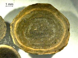
Fluid flow: Froude and Reynolds numbers

Describing sedimentary rocks; some basics

Measuring a stratigraphic section


Subaerial deposits

Volcaniclastic avalanch deposits inerfingering with reworked debris deposited from stream torrents


Lahars from the flanks of Karioi volcano, NZ, that entered the sea (Pliocene)


Taranaki lahar (bottom) and run-out mounds


Prehistoric Ruapehu lahar buried by airfall deposits

Crowsnest volcaniclastics showing fluvial reworking


Crowsnest Volcanics stacked lahars separated by thin rippled, fluvial volcaniclastic sandstone


Subaqueous deposits

A stack of submarine, high density debris flows sourced from the flanks of Miocene volcanoes, west NZ


Volcaniclastic debris flows in Miocene Waitemata Basin, NZ, also containing rafts of ripped up turbidite sandstone


A mega block of jointed baasalt in a volcaniclastic debris flow, Miocene, NZ. The block has settled differentially into the underlying turbidites


Volcaniclastics turbidites from the Paleoproterozoic Belcher Islands.


Two stratigraphic sections containing possible antidune bedforms in fine ash, associated with volcaniclastic turbidites. The steep face of each is that which is inferred to have migrated upstream - to the left in both images. Lower flow regime ripples indicate general flow in the opposite direction - to the right.
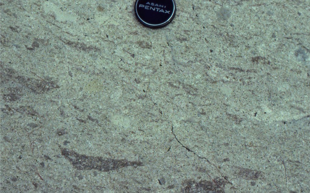
Two stratigraphic sections containing possible antidune bedforms in fine ash, associated with volcaniclastic turbidites. The steep face of each is that which is inferred to have migrated upstream – to the left in both images. Lower flow regime ripples indicate general flow in the opposite direction – to the right.
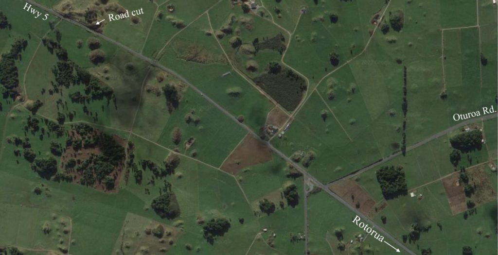
References

R.V. Fisher, 1961. Proposed classification of volcaniclastic sediments and rocks. Geological Society of America Bulletin, v. 72, p. 1409-1414.

R.V. Fisher, 1966. Rocks composed of volcanic fragments and their classification. Earth Science Reviews, v. 1, p. 287-298. Both papers by Fisher are classics on the subject.

R.V. Fisher, 1984. Submarine volcaniclastic rocks. Geological Society, London, Special Publications, 16, 5-27

C. Sohn & Y. K. Sohn, 2019. Distinguishing between primary and secondary volcaniclastic deposits.  Nature, Scientific Reports volume 9, Article number: 12425 Open Access. A discussion and addition to the White & Houghton classification.
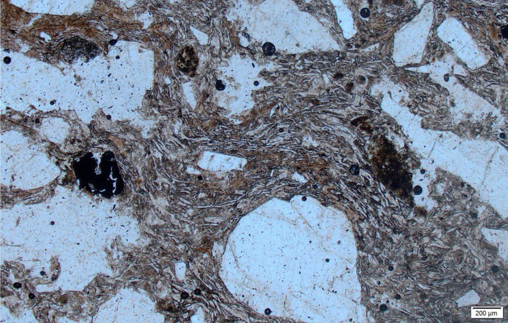
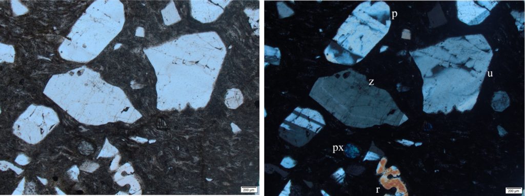
J.D.L White and B.F. Houghton, 2006. Primary volcaniclastic rocks. Geology, vol. 34, Issue 8.

Facebooktwitterlinkedininstagram
Facebooktwitterlinkedin

Volcanics in outcrop: Lava flows

Facebooktwitterlinkedininstagram

Columnar jointing in Edziza volcanics, northern British Columbia

A look at lava flows in outcrop

This is part of the How To… series  on describing rocks – in this post describing and interpreting lava flows in outcrop. Although the series focuses on sediments and sedimentary rocks, I have added these posts on volcanics because of their importance to sedimentary basins and basin stratigraphy.

Volcanic eruptions catch our attention, even the least violent. One of the more spectacular  recent effusions saw the east rift zone of Kilauea Volcano spew highly mobile basaltic lava from May 3 to September 4, 2018, destroying property and infrastructure. Terrifying for residents, morbidly thrilling for scientists.

Eruptive centres within sedimentary basins or along their margins act as dynamic loads that contribute to basin subsidence, effect geothermal gradients that can alter the conditions for organic and inorganic diagenesis, and contribute sediment. Lava flows are common additions to the stratigraphy of many sedimentary basins. The erosion of lava flows also produces debris that is reworked and redeposited by subaerial and submarine sediment gravity flows, and fluvial systems.

The images that follow illustrate some of the outcrop characteristics of lava flows and pillow lavas, organized thus:
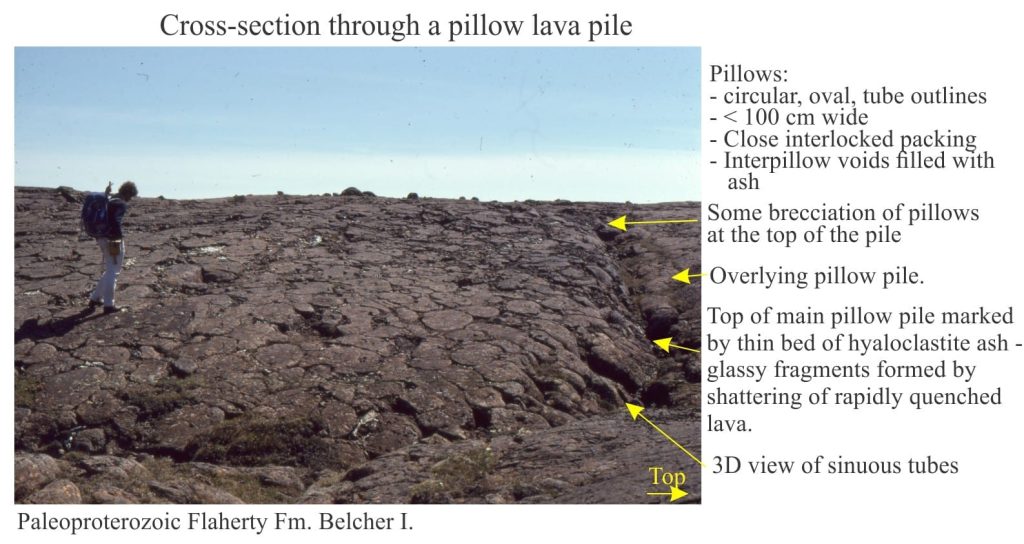
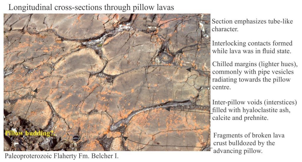
  • flow-base structures
  • flow top structures
  • internal structures
  • pillow lavas

Fragmented debris such as autobreccias and peperites are classified as Primary Volcaniclastics, but are included here because their formation is directly associated with flowing lava. The first diagram, cobbled together from White and Houghton (2006) summarizes this association of structures and processes.

Terminology for primary volcaniclastics proposed by White and Houghton, 2006


Additional photos of volcanic rocks and volcaniclastic facies are gathered in the Atlas of Volcanoes and Volcanic Rocks.


Related links in this series on outcrop descriptions

Accretionary aggregates and accretionary lapilli

Ignimbrites in outcrop and thin section

Block and ash flows

Volcanics in outcrop: Pyroclastic density currents

Volcanics in outcrop: Pyroclastic fall deposits

Mount St. Helens: 40th Anniversary

Volcanics in outcrop: Secondary volcaniclastics

Sedimentary structures: Alluvial fans

Sedimentary structures: coarse-grained fluvial

Sedimentary structures: fine-grained fluvial

Sedimentary structures: Mass Transport Deposits

Sedimentary structures: Turbidites

Sedimentary structures: Shallow marine


Other useful links

Describing sedimentary rocks; some basics

Measuring a stratigraphic section


Lava flows: base of flow structures

flow base pipe vesicles


flow base peperite


Lava flows: flow-top structures

modern and ancient ropey lavas


lava flow top breccia


lava autobrecciation


Lava flows: flow interior

tiered columnar jointing


entablature in lava flows


colonnade jointing in lava flows


flow banding in rhyolite


Pillow lavas

pillow lava piles


lobate pillow lavas


inter pillow voids


pillow lava feeder tube

References

J.D.L White and B.F. Houghton, 2006. Primary volcaniclastic rocks. Geology, vol. 34, Issue 8.

Many Volcanology text books are oldish, but no less excellent for all that. And as far as book prices go, not too expensive. Here are three excellent titles. Of course there are newer more expensive titles…!

L. Parfitt, and L, Wilson, 2008. Fundamental of Physical Volcanology.John Wiley & Sons, 256 p.

H-U, Schminke, 2004. Volcanism. Springer, 324 p.

Williams, and A.R. McBirney, 1979. Volcanology. Freeman, Cooper & Co, 397 p.

Facebooktwitterlinkedininstagram
Facebooktwitterlinkedin

The Pink and White Terraces, Magic Lanterns, and 19th Century Narratives

Facebooktwitterlinkedininstagram

White Terraces, painted by Charles Blomfield 1884

Preamble

A collection of late 19th century lantern slides made by Arthur Whinfield, a native of Worcester, England, has recently been restored and digitized.  I was alerted to the Whinfield collection by an old friend Justin Hughes, an archaeologist working in Worcester, UK, who indicated that the collection contained several slides of the famed Pink and White Terraces near Rotorua, New Zealand. These iconic geothermal wonders were destroyed by the eruption of Tarawera, on June 10, 1886.

Lake Rotomahana, in the shadow of Tarawera volcano, looks peaceful enough. Its waters are ruffled only by wind and the wakes of small boats. No hint of impending doom. No hint of the destructive explosions 132 years ago, eruptions that completely changed the local landscape, destroyed a village and its inhabitants, and obliterated a geological icon – the Pink and White Terraces.

New Zealanders look upon the Pink and White Terraces with a kind of fondness, even though no one alive has seen them. Mineral-rich waters spurting from geothermal springs and erupted from geysers above the former Lake Rotomahana, deposited silica in a cascade of rimmed terraces and pools; ever shrouded in steam. As their name indicates, there were two sets of terraces. The larger White Terraces descended 25m, stair-like, into the lake.  Their pink counterparts were terraced through 22m. Mineral content was more pronounced in the pink variety, with precipitation of arsenic and antimony minerals, and gold.

The terraces disappeared on June 10, 1886. Eruption of Tarawera was focused along a 17 km rift that extended from the volcano summit, through the terraces, and into Lake Rotomahana. Whether the terraces were obliterated, buried, or partly submerged in modern Lake Rotomahana is still debated.

By all accounts the terraces were spectacular; witness the written testimonies of geologists (like Ferdinand von Hochstetter in 1859) and Victorian gentlefolk, renditions in oil and water-colour (like the Blomfield painting above), and photographs – grainy, black and white, tinted amber with age. This was the late 1800s, and photography was in its infancy, the act of recording an image a laborious process.

Enter Arthur Whinfield. Whinfield was a peripatetic photographer who in the 1880s captured the magic of cities and landscapes in the Americas, Asia, Africa, Europe, Australia, and New Zealand. Part of his legacy resides in a collection of lantern slides (more than 2100 of them) that were donated to the Worcester Diocesan Church House Trust by his wife in 1918. A century later, in partnership with the Worcestershire Archive and Archaeology Service, the slides have been restored, digitized, and made available for public display. Included in the collection are 11 glass slides of the Pink and White Terraces, and the aftermath of the Tarawera eruption.

Whinfield took many of the photographs he used in his slides, but also borrowed from other photographers, and this seems to have been the case for several Pink and White Terraces images.  Te Papa Tongarewa  (the New Zealand National Museum) has an extensive, publicly accessible collection of photographs, paintings and prints related to the Terraces. I was able to identify individual photographers in some of the slides from the Te Papa collection.

Click on each image below for a larger format, then use the back-click arrow to return to the article.

The classic image of the Pink Terrace with Maori guides (or is this a family scene?) and a canoe in the foreground is shown below. This iconic photograph was taken by Burton Brothers Studio in 1885, and later used by Muir and Moodie Studio in a popular postcard (early 1900s; one penny postage required). Whinfield’s slide (left) is a copy of this scene (acknowledging the photographer on the lower left corner).


Whinfield slide left; Muir & Moodie postcard right


Moodie and Muir also produced a postcard from the White Terraces image below (left); the colour would have been added by hand to the printed photo. The Whinfield slide (right) is an uncoloured version of this image (compare the shape of the steam clouds at the top).  The terrace flights are nicely portrayed in this slide.


Muir & Moodie postcard left; Whinfield slide right


One of the more panoramic views of the White Terraces shown by Whinfield (left) is similar to a photograph taken by Burton Brothers in January-May 1886 (in the Te Papa collection) but is viewed from a lower elevation and records a different steam profile; the original photographer may have taken more than one shot from this location (I have not been able to determine who the photographer was for Whinfield’s slide). Here the terraces clearly dip their toes in Lake Rotomahana.  The terraces were a popular tourist attraction, in part because bathing was possible in the lower pools.


Whinfield slide left; Burton Brothers photo right


The original black and white photograph for the three slides below (Pink Terraces), was taken by Charles Spencer.  The three Whinfield slides are identical, with the right image slightly enlarged and a mirror of the other two. The view provides some detail of several small pools that appear to have been filled completely by silica.


The two slides below show detail of White Terrace pools and the intricate patterns wrought by precipitation of silica.  Dark stains daubed on the pool walls may have been algae. I have not been able to determine the attribution of either slide. The slide on the right is labelled ‘White Terrace Crater’ and may have been taken close to one of the active geysers near the top of the terraces.


Whinfield’s slide (below, left) showing the aftermath of the eruption at McRae’s Hotel is slightly different to one taken by photographer George Valentine (1886, McRae’s Hotel and Sophia’s whare) – the man on the right in Valentine’s image has his arms folded; in Whinfield’s slide they are not. The viewing angle is also slightly different – the ladder (foreground) is more oblique in the Whinfield slide.  The hotel probably collapsed under the weight of volcanic ash. Other photographs (not in the Whinfield collection) show the back of the hotel to be demolished completely. The trees were also stripped of foliage.


Whinfield slide right; George Valentine photo right


The title of the slide below Rotomahana Looking to Site of Pink Terrace, indicates a view towards the former terrace, or perhaps close to it, in the aftermath of the eruption. If the location is correct, the image is important because it shows that destruction of the Pink Terraces was complete. The Mounds of volcanic ash cover almost everything. Characteristic erosional rills suggest rain soon after the eruption, where surface water run-off redistributed the ash (probably towards the lake).  I could not determine who the photographer was.

Whinfield’s slides, recently brought to life, are delighting and informing audiences today, just as they must have done when he presented them to an eager 19th century public. These days we never think twice about the projection media at our fingertips. It seems almost to be part of our subconscious, but to Whinfield’s audiences there must have been a sense of excitement, awe, and puzzlement, not just in the images they were seeing, but the fact they were seeing them at all. The havoc wreaked by distant volcanic eruptions, was delivered to their living rooms by a rapidly developing technology.

The Whinfield Terrace collection may not contain photographs of his own taking, but this is not important. An iconic landscape was taking shape in people’s minds, a narrative in images. Folk who may never have left their own village became informed; witnessing the real world shaped by unimaginably ferocious forces – a kind of 19th century Scicomm.


I would like to hear from anyone who has additional information on the images in Whinfield’s slides, particularly information relating to the original photographers.


Credits: The Whinfield collection is owned by the Worcester Diocesan Church House Trust. I am grateful to the Trust for permission to use the digital images of the slides. Thanks also to Justin Hughes of the Worcestershire Archive and Archaeology Service for bringing the slide collection to my attention, for arranging to forward the images, and for his patience with my incessant questions.

Facebooktwitterlinkedininstagram
Facebooktwitterlinkedin