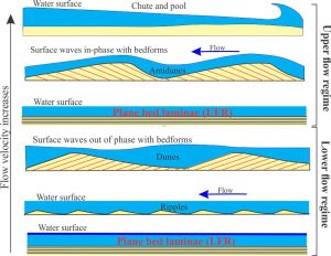

The iconic hydrodynamic flow regime model of Harms & Fahnestock 1965 – a useful starting point for interpreting ancient plane bed flow conditions
Laminated lower plane bed and upper plane bed sandstone lithofacies
Use this link to read the introduction to the lithofacies series.
General occurrence
Bedding in this pair of lithofacies is characterised by flat, relatively planar laminae a few grains thick, uninterrupted by cross stratification. They generally form in fine- to medium-grained sand. Laminae thickness is measured in millimetres.
Observations in modern flow systems, flume experiments, and the rock record presents us with two basic types of sand lamination that represent deposition at opposite ends of the hydrodynamic flow regime – one at lower flow plane bed, the other at upper flow plane bed.
The deposition of either sedimentary structure requires fairly specific hydraulic conditions.
Lower plane bed lithofacies
External structure
Laminae are flat, parallel, usually horizontal or close to it, and develop in fine- to very fine-grained sand; there may also be a component of silt. Laminae sets (i.e., multiple laminae) are usually a few centimetres thick. Laminae may be disrupted by bioturbation – common in marine environments, or root structures if the laminae are associated with organic paleosols. They are commonly interbedded or laterally associated with ripple and small-scale trough or tabular crossbed lithofacies.
Internal structure
Layering is flat and relatively uninterrupted in outcrop profiles. Carbonaceous plant fragments and platy minerals such as micas are commonly concentrated along laminae surfaces. If there is sufficient differentiation of platy grains, there may be a propensity for slate-like parting or breakage.
Thin section examination will usually show random orientation of framework grains such as quartz and feldspar, but preferred orientation of mica grains.
Formation – hydraulic conditions
Laminar structures that develop in sand beds indicate bedload transport and deposition. In this case, the criteria indicating relatively low energy flow include grain size and the preferred alignment along bedding of platy grains such as mica. Note that, despite its high specific gravity, the platy habit of mica confers a hydraulic response equivalent to much coarser grains of quartz and feldspar.
Observations in natural environments and in experiments indicate that the sandstone laminae form when flow is sufficient to initiate and maintain grain movement in a traction carpet but is insufficient to generate ripples. These conditions correspond to lower flow regime plane bed. Lower plane bed laminae occupy a restricted domain on the bedform stability diagram below. Laminar flow must be maintained; the water surface is essentially flat (low Froude and Reynolds numbers).
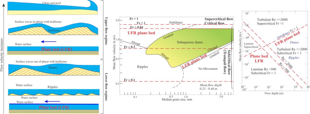

Summaries of the hydraulic conditions for deposition of upper flow regime bedforms, compared with other bedforms. Data for the graphical plots is mostly from flume experiments.
1- Flow Regime (left); after J.C. Harms & R.K. Fahnestock, 1965,
2- Median grain size and mean current velocities (centre); modified from Ashley, G.M. 1990,
3- Reynolds and Froude numbers as a function of flow depth and flow velocity (right); modified slightly from J.R.L. Allen,1992, Fig. 1.21.
Plane bed fields are indicated in bold red type.
Common environments
Lower plane bed laminae can potentially form in marine and non-marine settings. However, the bedform occupies a fairly restricted domain on the bedform stability diagram which constrains the specific depositional environments. For example, it is unlikely the laminae would form in either fluvial or tidal channels, or in many coastal settings (in contrast with upper flow plane bed laminae – see notes below). Deposition of laminae may take place in the lower, deeper part of the shoreface if tidal flux is sufficiently weakened. However, in this case the preservation potential of the lithofacies might be lessened by storm surge disruption (evidenced by hummocky cross-stratification) and bioturbation.
In terrestrial settings, the most common occurrence of lower flow plane bed laminae is across flood plains, where sediment laden storm waters breach channel margins. The ability of overbank flow to move sediment bedloads and suspended loads decreases with increasing distance from the channel margin. The lithofacies can also overlie point bars in fine-grained, low sinuosity rivers where it may be associated with paleosols and coal-bearing strata.
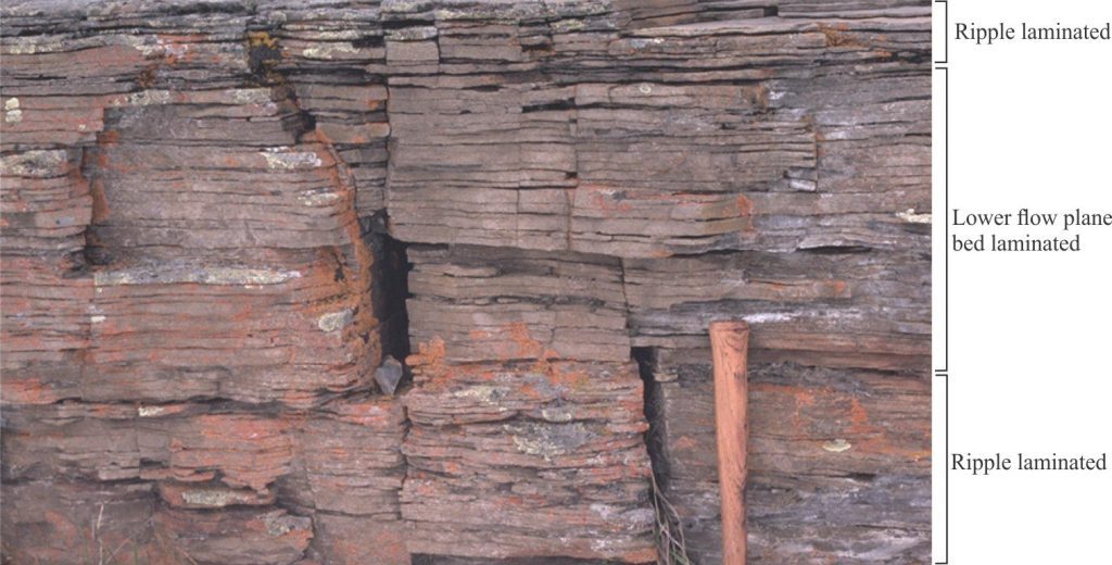

An interval, about 35 cm thick, of lower plane bed laminae in fine- to medium-grained fluvial overbank sandstone, overlain and underlain by sandstone containing low amplitude ripples (ripple lithofacies). Parting along bedding reveals significant amounts of carbonaceous plant fragments. There is also some mica. Cretaceous Kootenay Group, Alberta foothills.
Upper plane bed lithofacies
External structure
Parallel laminated sandstone is found in several depositional environments – fluvial, shallow marine, and some sediment gravity flows in marine and lacustrine settings. The common grain size of fine to medium sand is similar to that observed in lower plane bed deposits. Laminae are flat, horizontal or inclined, and occur in parallel sets measured in centimetres to decimetres thick where individual laminae are a few millimetres thick.
One sedimentary structure that distinguishes upper plane bed from lower plane bed laminae is parting lineation. Parting here refers to the splitting of laminated sandstone along bedding; lineation refers to the series of subparallel grooves and ridges, one to two grains thick, on exposed bedding. The long edges of both grooves and ridges approximately parallel the sediment transport direction – a useful indicator of paleocurrent flow although the actual flow direction is ambiguous unless there is corroborating evidence from other sedimentary structures.
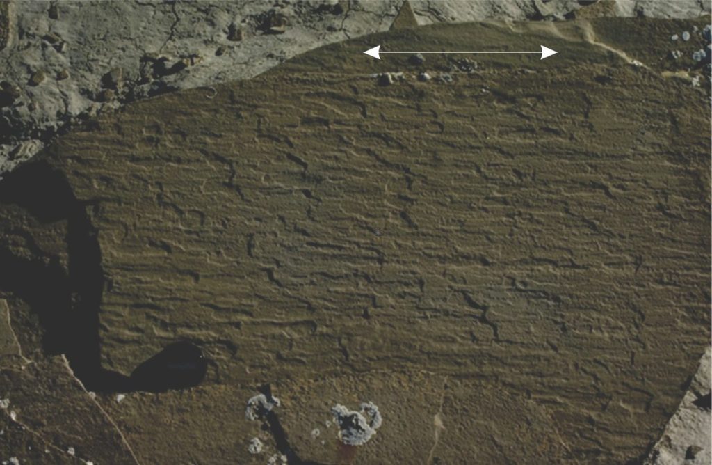

Parting lineation in Paleogene distributary channel deposits, Canadian Arctic. The arrow shows two possible paleocurrent flow directions. Resolution of actual paleoflow direction can only be determined from associated crossbed lithofacies.
Internal structure
Parting lineation is only seen on surfaces exposed by splitting along the plane of the lamination. The lineation is caused by the alignment of grains about their long axes. Examination of oriented thin sections by McBride and Yeakel (1963; PDF available) demonstrated that the mean azimuth of quartz grains having elongations >2:1, closely paralleled the measured azimuths of parting lineations in the same sample. The closeness of fit was confirmed by Potter and Mast (1963) who noted the parallelism of parting lineation and associated crossbed azimuths.
Low density carbonaceous fragments are sparse on laminae surfaces; mica is noticeably less common compared with low-flow plane bed laminated sandstone.
Formation – hydraulic conditions
Upper flow regime plane bed laminae are deposited at flow velocities greater than those required for dune bedforms, but less than conditions that produce critical flow and the transition to antidunes. J.R.L. Allen’s (1992) explanation for parting lineation formed under these conditions is that small-scale, elongate vortices develop parallel to the direction of flow – the vortices form close to the sediment-fluid boundary and are responsible for creating streaks of grains along the flow boundary. Grain alignment is thought to occur within these streaks.
An alternative explanation offered by C. Paola et al., (1990), based on flume experiments that used high speed photography, posits the deposition of laminae associated with migration of very low-amplitude bedforms that form in response to small-scale turbulent fluctuations close to the flow boundary, followed by a ‘smoothing’ process.
Common environments
Upper flow plane bed lamination is relatively common in the rock record. It can form in fluvial channels under conditions where flood levels and flow velocities decrease rapidly – a prolonged falling stage may result in lower flow regime bedforms reworking the earlier deposited sands. Channels responding to flash floods can also produce this lithofacies. The proximal parts of crevasse splays, fan-shaped sand bodies that form when channel levees are breached by storm flows, also contain the laminated sand facies. The lithofacies has been found on the accretionary surfaces of sandy point bars, usually with shallow dips towards the channel (Miall, 2006); associate lithofacies include tabular and trough crossbeds, ripples, and scour surfaces.
Laminated sands with parting lineations and shallow seaward inclinations are common in the wave swash-backwash zone of sandy beaches. The lithofacies here is commonly associated with low-angle planar crossbedding. In marine environments the lithofacies is usually found near the top of coarsening-upward, prograding shoreface to beach successions.
Parallel lamination is very common in turbidites where it comprises the B division of Bouma sequences. However, deposition in this case is from a turbulent suspension, unlike the fluvial and beach examples noted above. B-division laminae are part of a continuum of changing flow dynamics as the degree of turbulence, flow velocity, and concentration of suspended sediment all decrease with time and flow run-out. The formation of laminae and associated parting lineations indicate a significant degree of shear at the boundary between the turbulent suspension and the accreting bed.
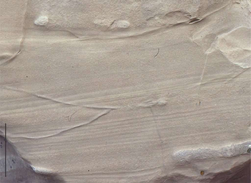

Parallel laminated sandstone in the B division in an Early Miocene turbidite. Individual laminae range from about 5 to 10 millimetres thick. North Auckland, New Zealand.
Other posts in the series
Sedimentary lithofacies – An introduction
Ripple lithofacies: Ubiquitous bedforms
Ripple lithofacies influenced by tides
Tabular and trough crossbedded lithofacies
Low-angle crossbedded sandstone
Hummocky and swaley cross-stratification
Lithofacies beyond supercritical antidunes
Subaqueous dunes influenced by tides
Introducing coarse-grained lithofacies
