Tag Archives: parting lineation

The hydraulics of sedimentation; Flow Regime

Facebooktwitterlinkedininstagram

This post is part of the How To… series

We introduce some basic hydraulics of sediment movement, bedforms and the concept of Flow Regime.

Ripples and dunes form when a fluid (usually water or air) flows across a sediment surface. Structures formed by air flow are called subaerial ripples or dunes; those in water have the qualifier subaqueous. These structures are given the general name bedform. The construction of bedforms requires certain conditions:
–    The sand must be cohesionless (i.e. grains do not stick together).
–    Flow across the sediment surface must overcome the forces of gravity and friction, and
–    There is a critical flow velocity at which grain movement will begin; this also depends on the mass of individual grains, and to some extent their shape.

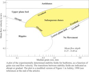
A plot of bedform types with respect to grain size and flow velocity.

Ripples and dunes form under a relatively limited range of flow conditions. We can illustrate this in a graph of flow velocity against grain size, plotting areas on the graph that correspond to bedform growth. Most of the data for plots like this are derived from flumes where experimental flow conditions can be monitored closely. The plotted distribution shows that bedforms can be categorized according to flow and sediment conditions. This partitioning of bedforms was used to construct the Flow Regime hydraulic model, first published in the now classic 1965 paper by J.C. Harms & R.K. Fahnestock and used widely ever since.

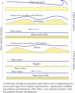
Flow characteristics and beforms in the flow regime hydraulic model, from Harms and Fahnstock, 1965.

The Flow Regime model considers three fundamentally different states of flow:

  • No bed movement where there is too little energy in the system to initiate and maintain sand grain movement,
  • A Lower Flow regime in which all common bedforms develop. Here, plane bed (basically parallel, planar laminae with no ripples) represents the lowest velocity, or energy conditions where sediment movement is initiated. It has been observed in flumes and in natural channels that the size of bedforms increases from ripples to large subaqueous dunes in concert with flow velocity. Dune type also changes from two dimensional structures (straight crests and planar crossbed bounding surfaces), to three dimensional structures that have sinuous, arcuate and lunate outlines and spoon or scour-shaped bounding surfaces (commonly seen as trough crossbeds).
  • An Upper Flow Regime where the power of stream flow washes out ripples and dunes, replacing them with plane bed (this kind of plane bed commonly has parting lineations), plus antidunes, and erosional chutes and pools.
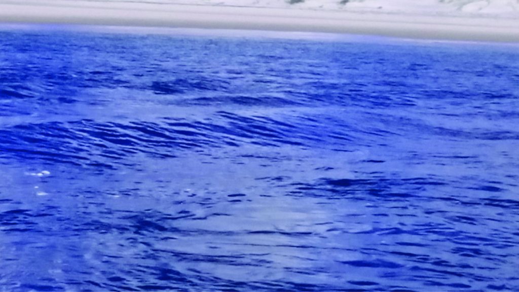
  • As stream flow increases the transition from Lower to Upper flow regime produces one of the more interesting bedforms – antidunes. They are mostly found in shallow channels (e.g. fluvial and tidal channels). You can recognize that this transition has taken place when you see standing surface waves – watch closely and you will see the waves migrate upstream. Antidunes are the bedforms that develop immediately below standing waves (the two are in-phase). If high flow is maintained, the antidunes will also migrate upstream. However, once flow slackens they tend to wash out; the preservation potential of antidunes is low.


Standing waves in a tidal channel.

The example above shows standing waves in a tidal channel on an out-going tide. Tidal flow is to the left; standing wave migration is to the right (Mangawhai Heads, North Auckland).

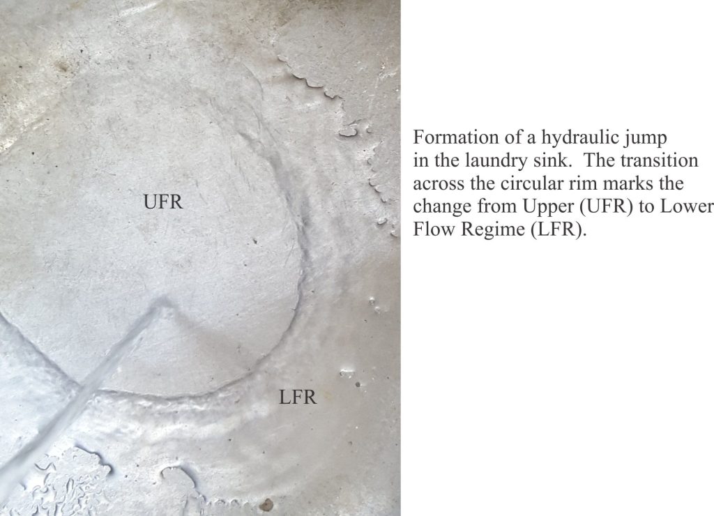
  • Hydraulic jumps: The transition from Lower to Upper flow regime passes with a change in bedform, in particular washing out of subaqueous dunes, but there is no sudden break in surface flow – the transition is reasonably smooth. This is not the case for an Upper to Lower flow regime transition that is marked by an abrupt increase in water level and turbulence – a hydraulic jump. Hydraulic jumps can be thought of as standing waves. They are caused by a reduction in Upper Flow Regime velocity, a change in stream-bed gradient or water depth, or combinations of all three.

A kitchen sink demonstration of a hydraulic jump

You can generate a hydraulic jump in your kitchen or laundry sink, so long as the sink floor is reasonably flat. Turn on the tap until you see a flow pattern like the one in the image above. Flat laminar flow is generated by the downward force of tap water – this is the plane bed. The hydraulic jump is located where the flow changes abruptly, with an increase in surface amplitude. Beyond the jump is lower flow regime flow.

We can use the Flow Regime concept in the field as a quantitative indicator of changes in paleoflow in time (i.e stratigraphically) and space (laterally).  For example, a stratigraphic sequence that shows a layer of ripples overlain by a layer of trough crossbeds indicates that flow velocities, and hence stream power increased abruptly. What kind of paleoenvironment might this have occurred in? This is one of the central questions for any sedimentological analysis.

Here are a couple of important references:

Ashley, G.M. 1990. Classification of large-scale subaqueous bedforms: A new look at an old problem. Journal of Sedimentary Petrology, v.60, p. 160-172.

Harms, J.C. and Fahnestock, R.K. 1965. Stratification, bed forms, and flow phenomena (with an example from the Rio Grande). S.E.P.M. Special Publication 12, p. 84-115.


Some more useful posts in this series:

Identifying paleocurrent indicators

Measuring and representing paleocurrents

Crossbedding – some common terminology

Sediment transport: Bedload and suspension load

Fluid flow: Froude and Reynolds numbers

Fluid flow: Shields and Hjulström diagrams

Facebooktwitterlinkedininstagram
Facebooktwitterlinkedin

Identifying paleocurrent indicators

Facebooktwitterlinkedininstagram

Sedimentary structures that indicate paleoflow. Measuring and plotting paleocurrent indicators are treated in a separate post.

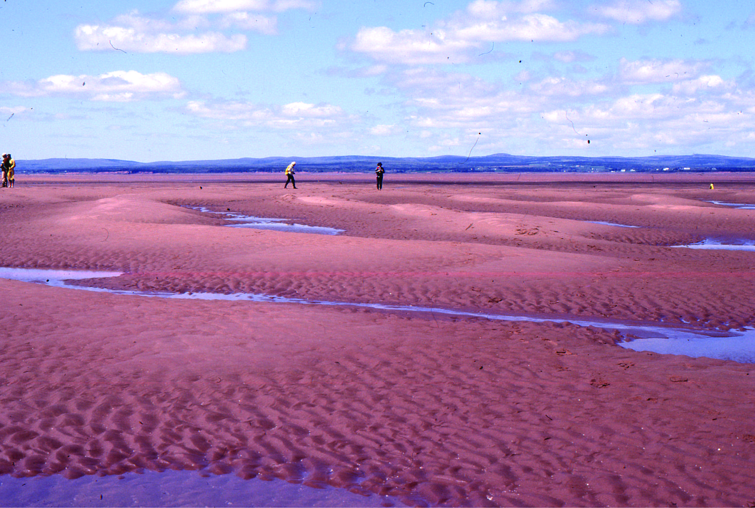
Subaqueous dunes and ripples in Bay of Fundy

This post is part of the How To… series

Sediment that is moved along a substrate (e.g. the sea floor, river bed, submarine channel, wind-blown surface) will commonly generate structures that record its passing.  Sedimentary structures that preserve directionality (paleoflow) are indispensable for deciphering whence the sediment came and where it went; for interpreting sedimentary facies (local scale) and sedimentary basins (regional scale). Paleocurrents are a measure of these ancient flows.

A single structure, such as a ripple will give a unique measure of paleoflow at a certain point in space and time. An important question for this single piece of data is – how relevant is it to the bigger picture of sediment dispersal? To get a sense of regional flow and sediment transport patterns, we need many measurements so that we can tease the overall pattern of flow from whatever local variations might exist.

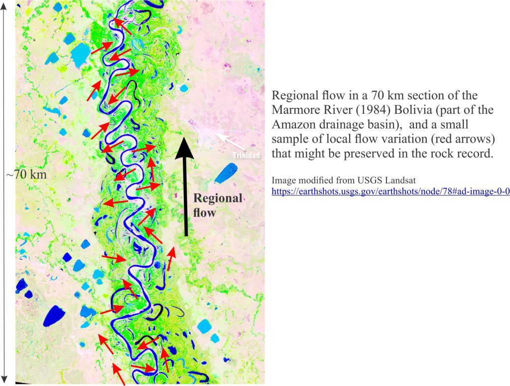
We can illustrate this central problem by looking at flow in a fluvial meander belt with depositional settings like the main channel (arrows), point-bars and adjacent flood plain. This snapshot in time shows clearly the huge variation in local flow directions. We also need to account for other ‘snapshots’ in time, because even at a local scale (e.g. one meander bend and point-bar), the directions of flow and sediment transport will vary from flood to low water stage. We can try to circumvent this problem if we measure a large number of flow directions over an equally large area of the river and floodplain.  In modern drainage basins this is straight forward but for the rock record, exposure is likely to be discontinuous and even structurally disjointed.

Landsat of Marmore meandering river in Bolivia. Flow to the north.

Structures indicating unique flow directions

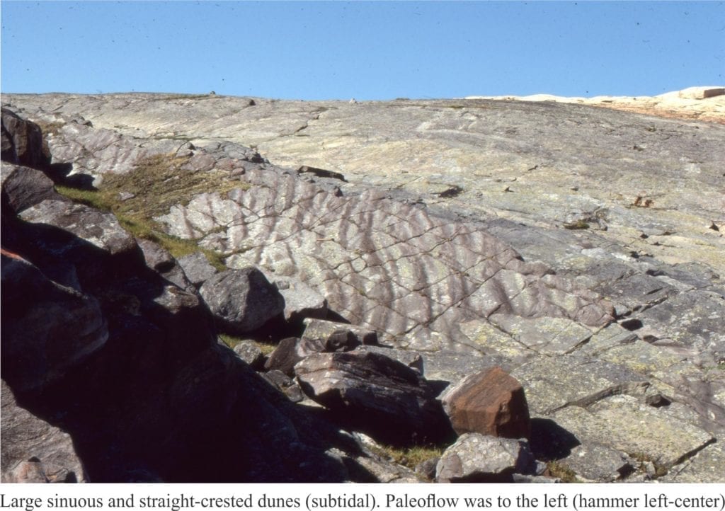
Subaqueous dunes and ripples: These bedforms are built by 2-dimensional (straight-crested) dunes and ripples. Hence, the boundaries between adjacent crossbed sets tend to be planar (cf. trough crossbeds). Flow direction is approximately at right angles to dune or ripple crests.
   Subaqueous dunes, or tabular crossbeds in Precambrian tidal flat deposits


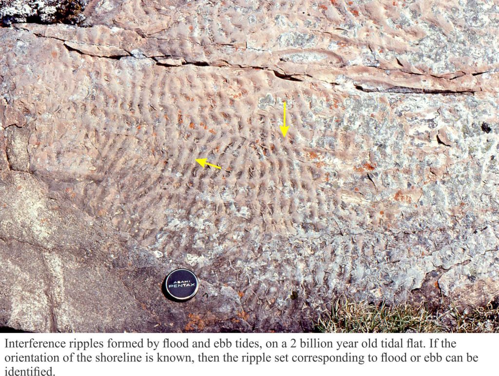
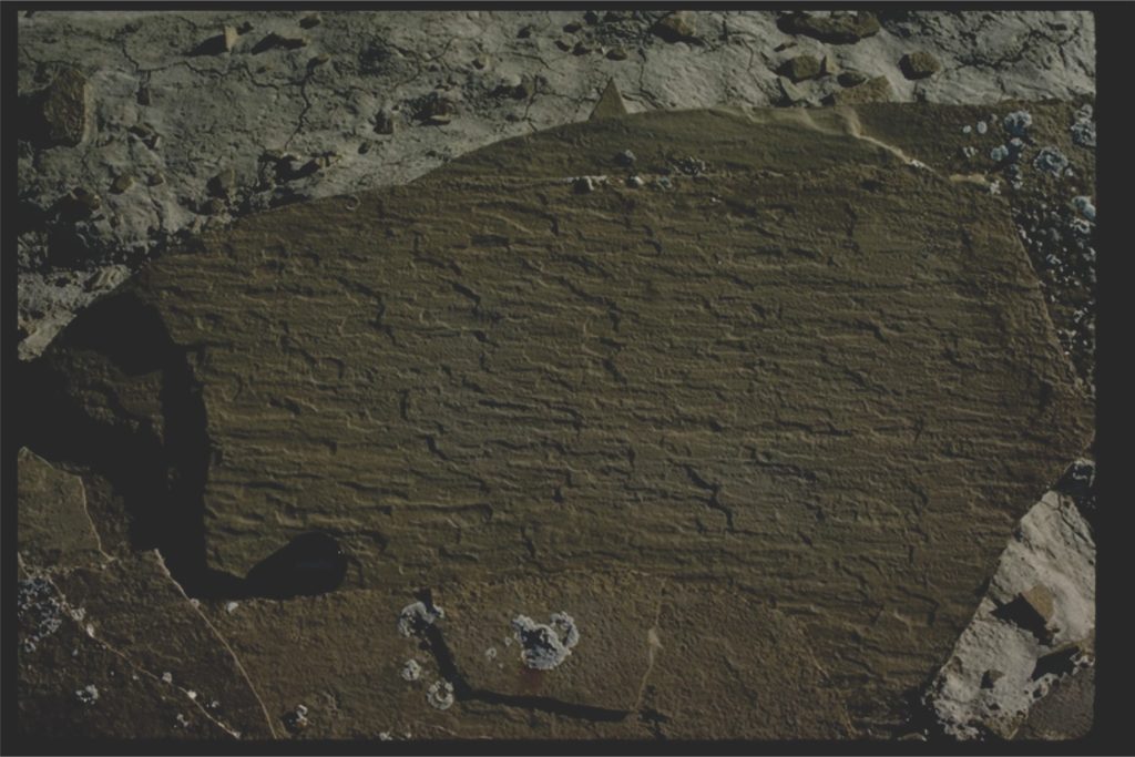
Precambrian interference ripples on a mixed sand-mud tidal flat


Trough crossbed, or 3D subaqueous dunes Spoon-shaped troughs filled by migrating, sinuous dunes produce trough crossbedding. This kind of crossbed is common in confined, channelized flow (e.g. fluvial and tidal channels). The mean flow direction is along the axis of the trough.

A view of trough crossbeds looking slightly oblique to bedding. The spoon-shape troughs are nicely exposed.


Tabular crossbed sets in sandstone. Flow was to top left.

Left: Festooned trough crossbeds exposed approximately parallel to bedding. Paleoflow is the direction of the hammer handle Proterozoic Loaf Fm.).  Right: Cross-section view of multiple trough crossbeds – only apparent flow directions can be surmised from outcrop (Eocene Buchanan Lake Fm.).

A caution about wave-formed ripples; This bedform does not arise from bedload transport in flowing currents, but from wave orbitals. Wave ripples are not paleocurrent indicators. However, wave ripple crests will be oriented approximately parallel to the strike of the ancient shoreline.


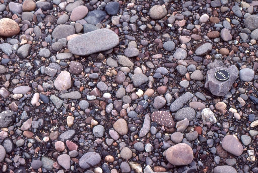
Imbrication  Flat and platy clasts are commonly oriented by strong currents, such that the ‘plates’ dip upstream. These fabrics are common in gravelly fluvial deposits.

Pebble imbrication on a modern river bank. Flow to the right.Imbricated platy cobbles and pebbles in a modern stream. Flow is to the right.


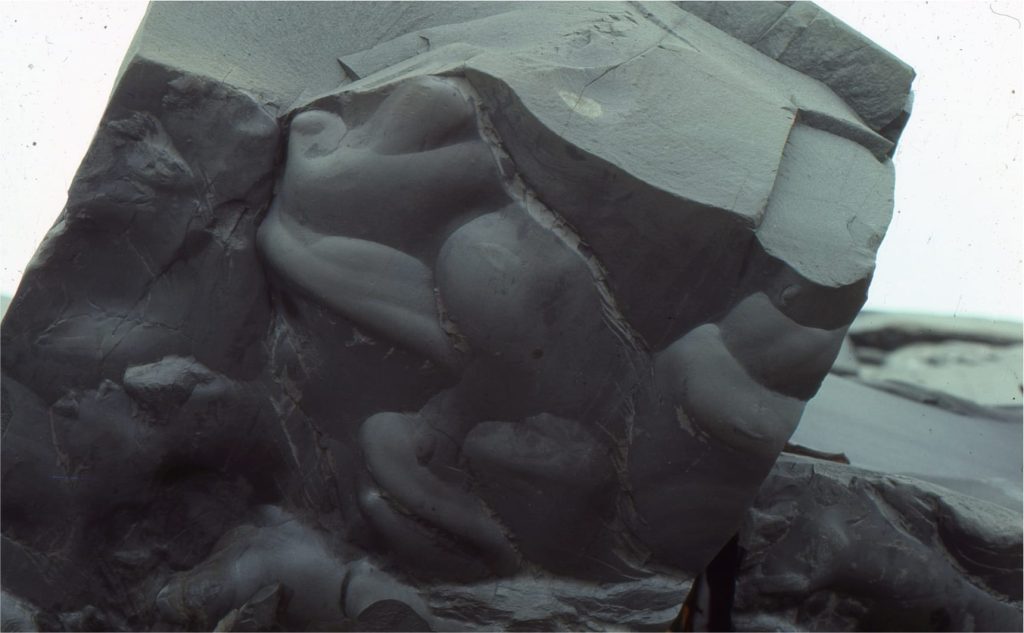
Flute casts  Flutes originate from erosion of a soft, commonly muddy substrate and are filled with sand – they are part of the overlying bed and are usually seen as casts on the sole of the overlying bed. Flow direction is towards the open, shallow end of the flute.

Large flute casts at the base of a turbidite Precambrian, Belcher Islands.Large flute casts on a turbidite bed sole (Omarolluk Fm, Belcher Islands). Flow was from top left to bottom right


Structures indicating ambiguous flow directions:

Groove casts  Objects dragged across a soft substrate by strong currents (e.g. bottom currents, turbidity currents) will scour linear grooves that become filled by the overlying sedimentary layer. Like flutes, they are usually seen as casts on the soles of beds. In the absence of other indicators, the two possible paleoflow directions are 180o apart.

Groove and skip casts on the sole of a sandstone bed.Groove casts on a bed sole, indicate flow in either direction. other criteria, like flute casts, are need to specify unambiguous flow directions.


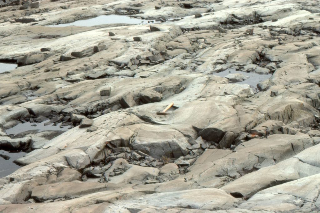
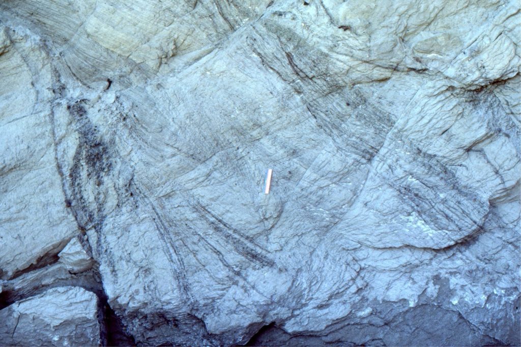
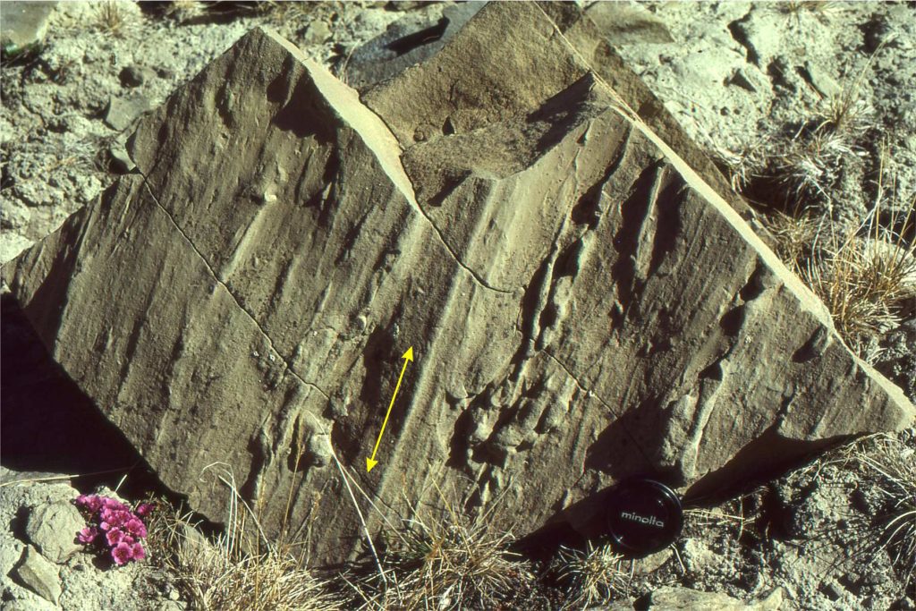
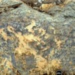
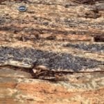
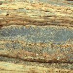
Parting lineation  These are subtle structures 2 or 3 grains thick, that are visible only on exposed laminated bedding. The word ‘Parting’ refers to rock breakage along planar laminations. Parting lineation is attributed to high flow velocities where the long axes of sand grains become aligned (in Flow Regime terminology this corresponds to Upper Plane Bed conditions). Paleocurrents are measured parallel to the long direction of parting, but like groove casts, are ambiguous.

Parting lineation in well sorted sandstone. Flow was either left or right.Paleoflow indicated in this parting lineation was either to the left or right.


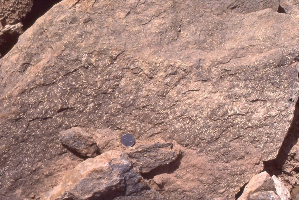
Current alignment  of elongate fossils, rod-shaped clasts, or bits of wood can generally be treated like groove casts in terms of their paleocurrent value. There are exceptions; for example turreted gastropods may be aligned with their apices pointing downstream.  The example shown here shows fairly consistent alignment of Permian Fusulinid foraminifera parallel to the prevailing flow (but the actual flow direction is ambiguous).

Current aligned Permian fusulinid foraminifera

The classic text that deals with paleocurrent analysis is – Potter, P.E. and Pettijohn, F.J. (1977) Paleocurrents and Basin Analysis. 2nd Edition, Springer-Verlag, New York, 425 p. 

Some more useful posts in this series:

Measuring a stratigraphic section

Measuring and representing paleocurrents

Crossbedding – some common terminology

The hydraulics of sedimentation: Flow Regime

Facebooktwitterlinkedininstagram
Facebooktwitterlinkedin

Atlas of sedimentary textures and fabrics

Facebooktwitterlinkedininstagram

The Atlas, as are all blogs, is a publication. If you use the images, please acknowledge their source (it is the polite, and professional thing to do). 

Texture in a rock describes the relationship of its components – grains, minerals, other chunks of rock – to one another.  In detrital sediments and sedimentary rocks, a distinction is made between clasts that form the framework (silt, sand, grit, pebble, cobble, boulder), and detrital sediment that is the matrix – matrix resides in the spaces between grains and usually consists of very fine-grained sediment, such as clays and silt. Detailed description of the matrix usually requires a microscope.

We can describe the framework in terms of the size (sand, cobble etc.) and shape of individual clasts (spherical, oblate, angular versus rounded), the proportions of different clast sizes (e.g. sorting), and the proportion of framework to matrix.  These are all useful descriptors of a sediment, but they can also provide valuable information on depositional processes, such as:

  • the degree of sediment reworking during transport (e.g. beach versus glacial diamictite),
  • depositional energy (e.g. river channel versus floodplain, beach versus estuary),
  • the removal, or winnowing of lighter, or hydraulically more buoyant mineral grains (e.g. micas), or
  • removal of mechanically less stable grains or minerals – for example quartz is mechanically more stable than feldspar because the latter usually has good cleavage.

Sedimentary fabric refers to detrital components that impart some kind of directionality to rock and sediment. It can be thought of as a vector, that has both magnitude (size, shape) and  direction (texture only has qualities like size, shape, proportion and so on). Thus, the alignment of clasts or fossils imparts a fabric (e.g. pebble imbrication in a channel, or current-aligned fossils).

Together, texture and fabric are important additions to a geologists toolbox, for description and interpretation.

Here are some related posts that you might find useful

Related links in this series on outcrop description

Sedimentary structures: coarse-grained fluvial

Sedimentary structures: fine-grained fluvial

Sedimentary structures: Mass Transport Deposits

Sedimentary structures: Turbidites

Sedimentary structures: Shallow marine

Describing sedimentary rocks; some basics

Measuring a stratigraphic section

Grain size of clastic rocks and sediments

Some controls on grain size distributions

This link will take you to an explanation of the Atlas series, the ownership, use and acknowledgment of images.  There, you will also find links to the other categories.

Click on the image for an expanded view, then the ‘back page’ arrow to return to the Atlas.


The images:


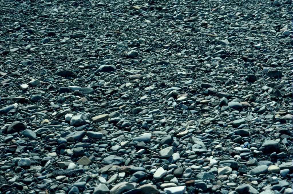
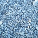
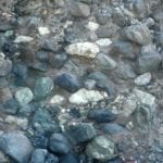
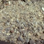
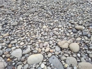
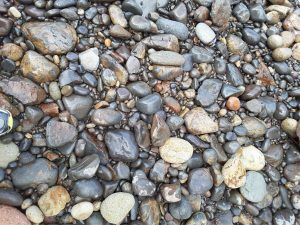
Beach gravels (Left, Haumoana, NZ; Right, Fundy Bay, Nova Scotia: both have clast-supported frameworks of well rounded, oblate to platey pebbles and cobbles.  Their texture and lack of fine matrix are in keeping with the high wave energy along these coasts.

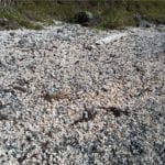
Beach storm ridge shell accumulations, clast (shell) supported.  The shells are predominantly gastropods, including abundant Struthiolaria.  There is no obvious preferred orientation of shells and shell fragments. Mangawhai Heads, NZ


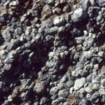
Exhumed surface of a Jurassic fluvial deposit. Pebbles of radiolarian chert are all well rounded, and most participate in a clast-supported framework.  Rounding of the pebbles must have taken place in a shallower water environment, probably fluvial.  Bowser Basin, northern British Columbia.


Here is an analogy for packing of well rounded, spherical to subspherical clasts, as in the chert conglomerate imaged above.


Contrasting debris flow textures. Left; matrix-supported clasts of radiolarian chert and mudstone rip-ups – this was a very muddy, cohesive debris flow. Right; mixed last-supported and matrix-supported clasts in a less cohesive, more fluid debris flow.  Bowser Basin, northern British Columbia.


Bouldery debris flow, with mixed clast- and matrix-supported frameworks. Dana Point, California.


Lower Miocene volcaniclastic debris flow, mostly matrix-supported but pockets of clast-supported frameworks. Waitakere Volcanic arc, west Auckland.


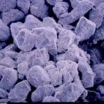
Scanning electron microsope image of a moderately  well-sorted sandstone, Ellerslie Fm, Alberta.  Sand grains show varying degrees of depositional rounding.  The fuzzy surface of most grains is caused by incipient diagenetic clays (illite-kaolinite), i.e. clays formed by chemical reactions after deposition. This rock has excellent porosity and permeability. the image width spans 3mm.


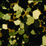
Thin section micrographs of a lithic sandstone (arenite). Left: plane polarized light, showing individual grain shapes and intergrain contacts.  The blue areas are pore spaces filled with blue resin. Right: Crossed nicols, showing quartz in various stages of extinction, lithic grains (speckled), and minor potassium feldspar. Ellerslie Fm, Alberta. Most grains here are about 0.2 – 0.3mm across.

check out this and related posts for an explanation of polarizing microscopy


Thin section micrograph, under crossed nicols of a calcite-cemented lithic sandstone, Ellerslie Fm, Alberta.  The calcite has a yellow-orange colour.  Most grains here are about 0.2 – 0.3mm across.


The fusulinid foraminifera incorporated into these Permian sediments, have all been aligned approximately parallel to the local paleocurrents (determined from crossbedded calcarenites).  South Bay, Ellesmere Island.


Modern river gravels containing abundant platy rock fragments that are aligned by the prevailing currents. The imbrication here indicates flow to the right.


Parting lineation in laminated sandstone forms when the long axes of sand grains, in layers a few grains thick, are aligned parallel to current flow directions.  The streakiness, or lines form when sandstone splits along the laminae. They are thought to form during upper flow-regime plane bed flow (high energy flow). Paleoflow in this example was either to the right or left; a decision as to which direction can only be determined from unidirectional structures.


Stone rosettes form on beaches where there is a plentiful supply of platy rock fragments – in this case much older shale.  The flat clasts are turned edgewise by wave action, and commonly are organised into crude radiating or stacked patterns (also called edgewise conglomerate). Similar structures can form from bivalve shells.  On some beaches they form extensive pavements.  Somewhat similar structures have been reported from periglacial regions.


An example of ancient stone rosettes, or edgewise conglomerate forming extensive pavements on a Proterozoic beach (about 2 billion years old). In this example (Mavor Fm., Belcher Islands, Hudon Bay), the thin slabs consist of dolomitized lutite crusts, formed probably in a supratidal flat, and subsequently ripped up by storm waves.

Here is a paper on these examples: Ricketts, B.D. and Donaldson, J.A.  1979: Stone rosettes as indicators of ancient shorelines: examples from the Precambrian Belcher Group, Northwest Territories; Canadian Journal of Earth Sciences, v. 16, p. 1187-1891


                          Profile of Proterozoic edgewise conglomerate pavement

Bedding cross-section views of ancient, Proterozoic stone rosette beach pavements.  The edgewise stacking of platy dololutite crusts is readily apparent.  A bedding view of the same structures is shown above.  Mavor Fm, Belcher Islands, Hudson bay.


Pavement of close-fitting, well rounded cobbles and pebbles, near Little Bay, Coromandel, NZ

Pavement of close-fitting, well rounded cobbles and pebbles, near Little Bay, Coromandel, NZ


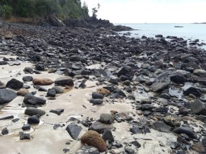
Poorly sorted, subangular to well rounded cobbles and sand on a beach, Little Bay Coromandel

Poorly sorted, subangular to well rounded cobbles and sand on a beach, Little Bay Coromandel


Angular andesite boulders in fine sand present a broadly bimodal grain population, Little Bay, Coromandel, NZ

Angular andesite boulders in fine sand present a broadly bimodal grain population, Little Bay, Coromandel, NZ

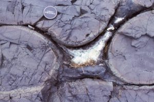
Geopetal structure in the interstice between pillow lavas. Base is filled with hyaloclastite fragments, the top with calcite spar. The contact between these two fills represents a horizontal surface

Geopetal structure in the interstice between pillow lavas. Base is filled with hyaloclastite fragments, the top with calcite spar. The contact between these two fills represents a horizontal surface at the time of deposition

Facebooktwitterlinkedininstagram
Facebooktwitterlinkedin