Tag Archives: pole to axial plane

Cleavage and cleavage-bedding intersections

Facebooktwitterlinkedininstagram

This post is part of the How To… series


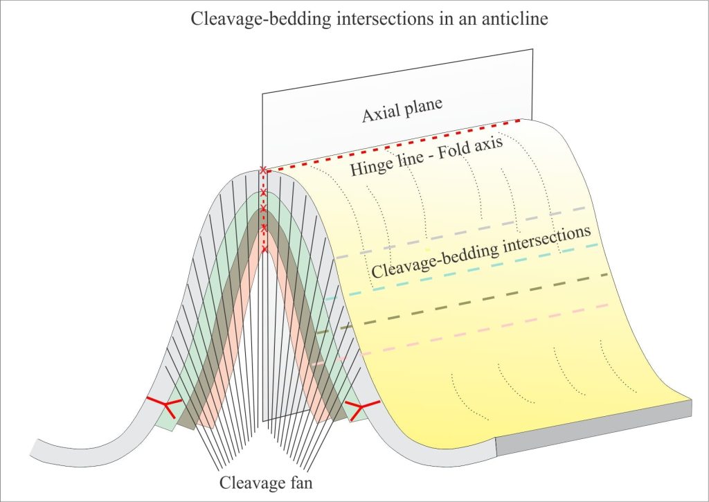
Diagram of cleavage fan intersections with bedding in an anticline

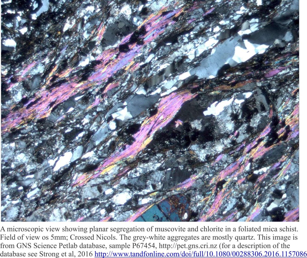
Cleavage is a fabric. It is a close, regularly spaced planar to curviplanar foliation. The term ‘cleavage’ derives from its propensity to split apart or cleave. Where cleavage is developed it is pervasive at both macroscopic (outcrop, regional map scale) and microscopic scales (thin section); in other words, it is a penetrative fabric. It is most commonly found in folded rocks that have been subjected to some degree of metamorphism – from relatively low-rank slate (slaty cleavage), to beautifully foliated schist.

Thin section view (crossed polars) of mica segregation in schist that results in cleavage

Cleavage is the product of shortening and to some extent a reduction in rock volume by dissolution during folding and metamorphism.  Cleavage planes are defined by an alignment of micas (hence the ability to cleave) that grow as other more labile minerals (e.g. clays, particularly illite) are recrystallized. The growth of mica crystals and progressive development of cleavage go hand in hand.

There is no void space between cleavage planes and although they are mechanically weak, the rock is continuous. Hence, cleavage differs fundamentally from joints. Joints also are regularly spaced, commonly pervasive planar structures, but they form by extension and brittle failure of a rock mass. This process results in void space, or fracture porosity that during burial will become the locus for precipitation of minerals such as calcite and quartz.

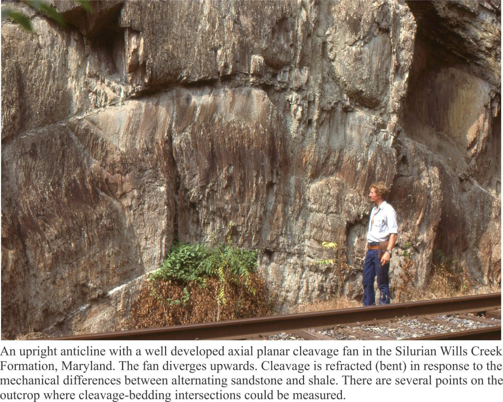
Axial planar cleavage fan in an anticline, Silurian Mills Creek Fm. Maryland

Cleavage has a geometric relationship with folds. Arrays of cleavage are commonly arranged as fans about axial surfaces and in tight folds cleavage closely parallels axial surfaces. Both cases are referred to as axial planar cleavage. Fans diverge upwards in anticlines and converge upwards in synclines. This relationship furnishes us with yet another tool for deciphering fold type and fold orientation.

  1. The intersection of a cleavage plane with bedding creates a lineation that is parallel to the fold axis. We can measure its trend and plunge.
  2. In upright folds, cleavage planes have dips steeper than bedding. Cleavage plane dip in overturned and recumbent folds may be less than bedding dips – if you observe this geometric relationship in outcrop then consider the possibility that the folds are overturned (S and Z parasitic fold orientation will be useful in this regard).
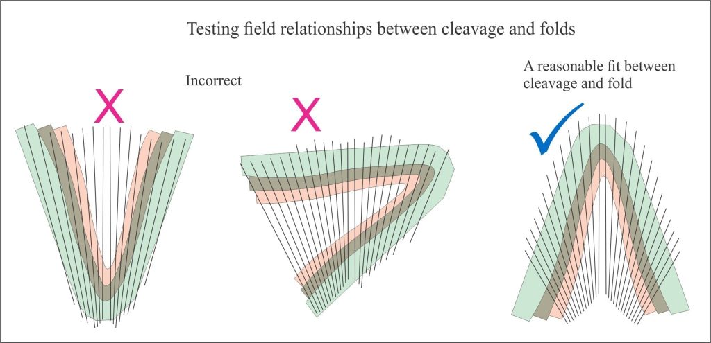
  3. Cleavage geometry can be used to determine the facing direction of beds such that we can go beyond an antiform-synform description and identify more specifically anticlines and synclines. A simple example is shown in the cartoon below.

Testing field relationships between cleavage and folded beds.

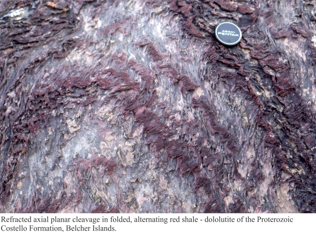
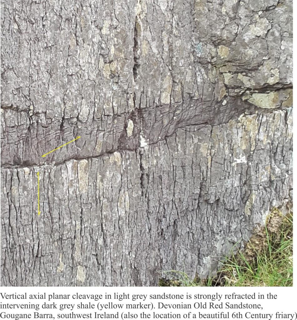
Cleavage is not always uniformly planar. In layered successions cleavage planes are commonly refracted or bent. The change in orientation reflects how different lithologies respond to stress; common examples of cleavage refraction occur in successions of alternating sandstone (mechanically strong) and shale (mechanically weaker). A couple of examples are shown below.

Refracted axial planar cleavage in Paleoproterozoic dololutites, Belcher Islands


Refracted cleavage in Old Red Sandstone, Gougane Barra, southwest Ireland

Other useful links in this series:

Measuring dip and strike


Folded rock; some terminology


Using S and Z folds to decipher large-scale structures

Facebooktwitterlinkedininstagram
Facebooktwitterlinkedin

Stereographic projection – poles to planes

Facebooktwitterlinkedininstagram

great circles


This post is part of the How to… series

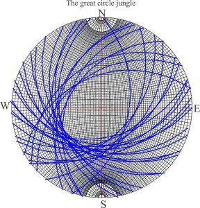
Stereographic projection is used in geology to decipher the complexities of deformed rock by looking at the relationships between planes and linear structures; their bearings (trends) and angular relationships one with the other. The data is plotted on a stereonet as great circles and points (Wulff and Schmidt nets). A stereonet can become pretty messy where there is a lot of data – a seemingly impenetrable maze of great circles. This is where poles-to-planes come into their own.

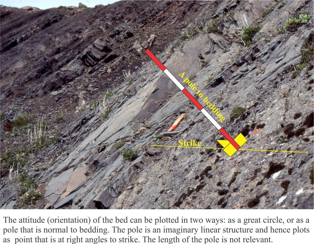
Instead of plotting the great circle to a planar structure like bedding, we plot its pole. Imagine this as a pole oriented at right angles to the plane. Because the pole is a linear feature, it plots as a point on our stereonet. As long as the pole is 90o to strike, it will contain all of the information in the associated great circle. We refer to this point as the pole to bedding (or any other planar feature). Poles to horizontal planes will plot at the centre of the stereonet; poles to vertically dipping planes at the perimeter. Poles to planes dipping at any other angle will plot within these bounds.

Imagine a pole to oriented normal to bedding. The point of intersection on a great circle contains all the information about the attitude of the bed

Imagine a pole to oriented normal to bedding. The point of intersection on a great circle contains all the information about the attitude of the bed

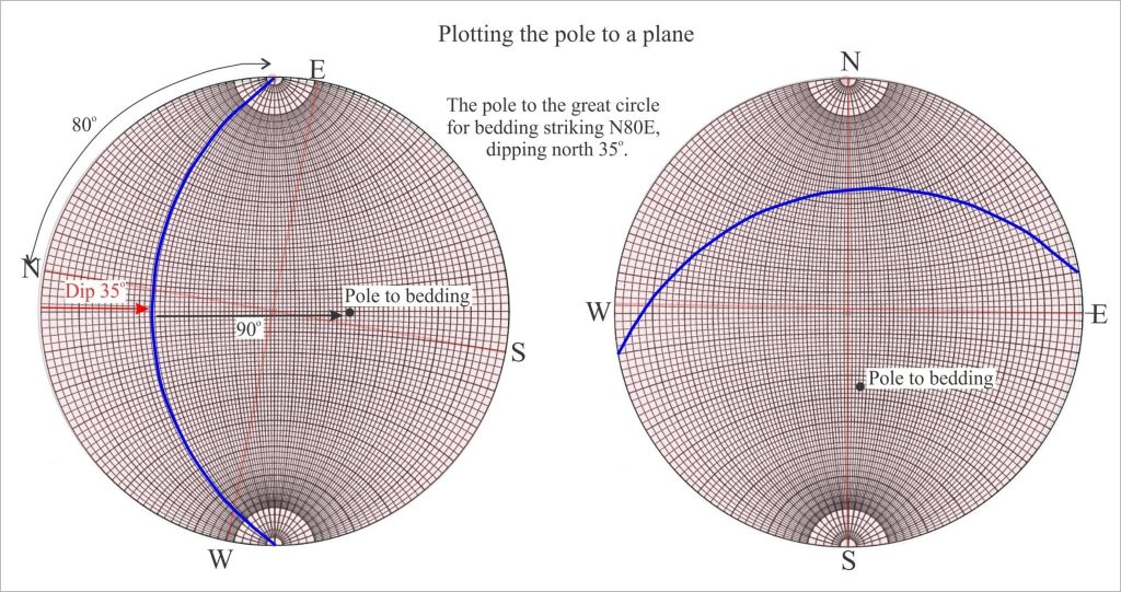
In the example below the orientation of a bedding plane is plotted on an overlay as a great circle. With the great circle pinned to N, count 90 along the W-E axis passing through the centre of the stereonet; this point is the pole.

Plotting poles to bedding no a stereonet


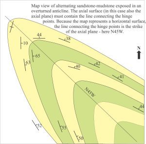
For cylindrical folds the poles to bedding on each limb will all plot on the same great circle (or close to it). The pole to this great circle corresponds to the β point – the fold axis, from which we can read its trend and plunge. Stereographic plots that use poles to bedding or other planes are called pi (π) plots. The utility of pi plots is illustrated in the example of an overturned anticline (the diagrams have been modified from D.M. Ragan, Structural Geology: An introduction of graphical techniques 1968, Figure 11.3).

map of overturned anticline with plotted dips and strikes that can be used to determine the orientation of the axial plane

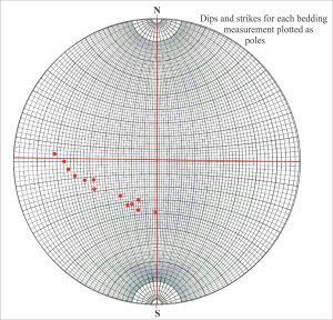
Dip and strike data on each fold limb are plotted as poles to bedding. We can also locate on the geological map the hinge points for each layer. The line connecting hinge points must lie on the axial surface. However, because our map view is horizontal, this line corresponds to the strike of the axial surface – another important piece of information. What we do not know about this structure is the orientation of the fold axis and the dip of the axial plane. The sequence of diagrams that follows shows the main tasks involved in solving this problem.

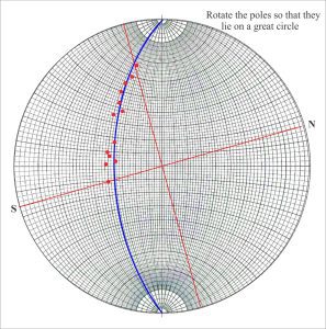
  • Find the great circle describing the poles to bedding by rotating a transparent overlay (make sure you mark the original N-S positions on the overlay).

Dip and strike for each measurement plotted  as poles to bedding                The poles for each bed dip and strike in the fold lie on a great circle

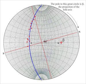
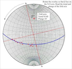
  • With the great circle pinned to North, count 90o from the circle along the east-west axis (the count must pass through the centre of the stereonet); this point is β, the fold axis.
  • Rotate the overlay counter-clockwise until β lies on the N-S axis. From North, read the fold axis trend and plunge.

                Stereographic determination of plunge and trend of the fold axis


Stereographic determination of plunge and trend of the fold axis

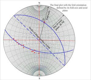
  • Plot the line representing the strike of the axial surface (N45W). The great circle containing this line must also pass through β.
  • With the second great circle pinned to North, read the dip of the axial surface.
  • Rotate the completed stereonet back to its original position.
The final plot of fold axis and dip of the axial plane

The final plot of fold axis and dip of the axial plane

You now have all the information you need to describe the orientation of the anticline.

Some other posts in this series:

Measuring dip and strike

Stereographic projection – the basics

Stereographic projection – unfolding folds

Using S and Z folds to decipher large-scale structures
Facebooktwitterlinkedininstagram
Facebooktwitterlinkedin